I always wanted to make a choke loaded mosfet class-a amplifier. I read CIRCLOTRON`s thread (my first class a amp) and got the idea of making my own...
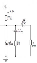
You can see on the schematic, that the amp will be loaded with 4 ohm speakers, iddle current is 4.5A and the dissipaton on the choke would be about 60W.
So:
1. the power of the iron core should be ...?
2.air gap should be...?
3.inductance should be ... mH?
4.How to calculate the optimal inductance and airgap ?
Thats "all" for now, I gess some of the experts round here
will help me?
thanks a lot and cheers!
Start with the value of the inductor. In theory, what you want is an 'infinite' inductor. In practice, you want an inductor which does not become an impedance which approaches the impedance of the load, at the lowest frequency you wish to transfer. For instance, taking 16Hz as the lowest frequency, and 4 ohms as the load, and, say, 12 ohms (3x load) as the inductor impedance at t his frequency, you get approx. 120mH.
Now, calculating the windings, core and gap is a whole different story, you need to start with a known core, but I'm really not apt enough in this area to give you a ready made calculation.
One thing you need to remember is that this sort of output stage swings below ground (which is the reason for using a choke!), so you need to provide appropriate drive voltage, that also swings below ground.
Slightly off-topic: you have asked about several projects you want to do, in detail. What has become of them? Many contributed with answers to your questions, but we never hear about any of the results of your work?
thanks ILIZMN!
I made two amplifiers (my construction,but classic) and sold them.They still work good. I needed extra money for the car. There`s a not very nice situation in Serbia and I think Croatia has the same problems...
I`m collecting the money for the the new amp:
Its gonna be my first class a amplifier. I`m gonna find some old iron cores on the (ne znam kako se kaze vojni otpad) and rewind them.
Do you know what should be the size of the core(EI).
IN my simulation i get 60W dissipaton on the choke and I think that even a 100W EI transformer core would be too small. I`ve seen circlotrons amp chokes and they`re gigantic!
I need to know what size of the core to buy.
cheers.
To ILIZMN: I see you know a lot abouy audio electronics and didn`t saw any of your designs on the forum. why?
bogdan_borko said:
Do you know what should be the size of the core(EI).
IN my simulation i get 60W dissipaton on the choke and I think that even a 100W EI transformer core would be too small. I`ve seen circlotrons amp chokes and they`re gigantic!
I need to know what size of the core to buy.
It will likely be huge, I doubt a 100VA mains transformer core will even come close. Also, you should not have 60W dissipation in the choke - this would mean your choke will have about 3 ohms of resistance, which would make it rather bad quality (too thin wire).
[/quote]
To ILIZMN: I see you know a lot about audio electronics and didn`t saw any of your designs on the forum. why? [/Quote]
Mostly because the times when I did several amps a year are behind me by a number of years. What I do these days is done as a job as well as some things I would ecventually like to sell, so there is the intellectual property issue. However, every once in a while I 'leak' something out
") if you read my posts carefully.
if you read my posts carefully.Unfortunately, due to some personal life complications as well as having to spend my vacation in a hospital, I am running way behind on my projects, one of which I wanted to put up here - so, hopefully, I still will, just much later than expected.
bogdan_borko said:does the choke loaded mosfet class a source follower need a bias circuit with thermal track?
Normally no - because the choke's internal resistance is typuically sufficient to provide a much higher voltage drop on it, than the thermal variation of the threshold voltage. Also, keep in mind this is a class A amp, there will not be much thermal variation to begin with (always runs hot
).Still, it may depend on what kind of driver you are going to use...
bogdan_borko said:You can see on the schematic, that the amp will be loaded with 4 ohm speakers, iddle current is 4.5A and the dissipaton on the choke would be about 60W.
That would be absolutely horrible. No way should that choke dissipate that much. You can get the DC resistance much lower, and therefore avoid having to capacitor couple to the speeks. Getting the DC offset below 0.5V or so won't cause any problems.
So:
1. the power of the iron core should be ...?
2.air gap should be...?
3.inductance should be ... mH?
4.How to calculate the optimal inductance and airgap ?
Thats "all" for now, I gess some of the experts round here
will help me?
thanks a lot and cheers!
The required inductance is easy: make this about 4 -- 5 times the load impedance. For 4.0R, that would come to: ~106mH. Winding a coil for that isn't going to be all that difficult. It will, however, be big and heavy since it'll need lots of iron, and large gage wire. With the power supply, these MOSFET parafeed amps aren't exactly portable.
- Status
- This old topic is closed. If you want to reopen this topic, contact a moderator using the "Report Post" button.
- Home
- Amplifiers
- Solid State
- L as a choke.