I have been known to make some dissapointingly pointless and unpopular threads due to the lack of experience that I have to endure. If this is one of them please at least post some good techniques! I want to design a good amp one day and I hope that that will not be so far away so please help me get up to date!
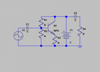
Okay okay, this circuit won't work as you have stated (using it as a common emitter).
==> If we bypass R3 with a capacitor to make the emitter at AC ground (just to make the math simpler), the common emitter's voltage gain is given as gm * Rout
where gm is the transconductance of the transistor, and Rout is the output resistance (seen looking out of the collector).
Your Rout is 0 because the collector sees an AC short circuit to ground through the supply voltage V1. The current that flows out of the collector will go down the V1 path, not the R4 and C2 path, because the V1 path has 0 resistance. Thus your voltage gain is 0.
Okay, forgot about the capacitor, I have to store this circuit in my head and it hasn't been used for a while. Thanks for the reply!
...So I need to put a resistor in series with the power source? I have seen that but figured it wasn't necessary. I guess battery's are capacitors so maybe that's why barely any of my circuits work! I'll keep that in mind... Thanks!
...So I need to put a resistor in series with the power source? I have seen that but figured it wasn't necessary. I guess battery's are capacitors so maybe that's why barely any of my circuits work! I'll keep that in mind... Thanks!
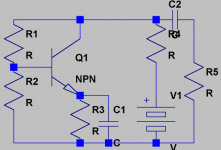
That looks much better.
To analyse it further vis-a-vis biasing (DC conditions), consider the voltage you'd find at the base. This will be the result of the voltage divider between R1 and R2.
R2
------------ x Vcc (collector supply voltage)
R2+R1
R1 and R2 must be small enough to allow the base to draw enough current without unduly influencing the bias voltage.
From the base voltage, subtract the junction voltage of 0.7V dropped across the base/emitter junction. This leaves the voltage across the emitter resistor (R3). Divide the voltage by the resistance to get the current.
The emitter current is the collector current plus the base current. Since the collector current is much greater than the base current, you could say that IC=IE.
You'll have chosen a desired collector current to suit your device, and a collector resistor to drop maybe half the supply voltage.
I have just laerned of something I was almost completely oblivious to from another thread-how to make a voltage/current dividing network. I summed up all the values in an equation, I am wondering if I made it right. Here it is:
(Vs/Ib)=A, (Vb/(Vs/Ib))=B, ((Vs/Ib)-(Vb/( Vs/Ib )))=R1, A=R2
Where:
Vs=supply voltage
Ib=needed base current
Vb=needed base voltage
I wasn't thinking that some current would flow through the base and maybe disrupt the dividing, but I'm not completely sure how this works yet, so please give me feedback. I believe how this works is you have the voltage divider which is two resistors (yeah, of course) in series with the power supply and these are varied as to give a voltage proportional to the supply voltage in their centerpoint. To adjust current, I would think that you would have to increase or decrease the resistors proportionally to each other, right? This is just to get a better understanding even though the equation does it all. Understanding is good! Others may not understand all that technobabble that you spout out when you tell them how to make their stereo sound good but sure helps you understand them when the skill is needed! Thanks!
Hi Kean,
for the two resistor voltage biassing you are discussing there is a guide for resistor values.
Find your collector current (Ic).
Read off the transistor gain (hFE) @ Ic.
Calculate the base current (Ib) = Ic/hFE.
now the rule.
The bias resistor string CURRENT ~= 10times the Ib.
This fixes the bias resistor values (using the resistor ratio) to get you a ball park figure to start fine tuning.
There is a downside to this method of biassing. The two resistors are connectted to PSU and ground. The impedance of both of these is near zero. The impedance seen at the base of the amplfying transistor is the base impedance in parallel with the upper resistor and in parallel with the lower resistor. This three parallel combination can be quite low as seen from the previous stage. The design decision becomes:- can the previous stage drive this input impedance?
keantoken said:I am new (sort of) to electronics and I am not too keen on transistor biasing yet.
So I would like people to post at least
a few good biasing techniques.
Good and useful topic!
( Should REALLY be in Solid State, moderators. )
We all need to bias all transistors ... or they wont do any job.
Not even MOSFETS!
-----------------------------------------
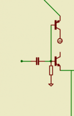
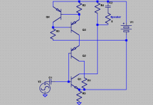
I have shown, in a previous topic in Solid State
a good way to use very high impedance and very precise
ACTIVE BIASING!
See picture below:
If is about same Current in PNP transistor, the biasing T,
as in the NPN transistor, working T
then
the base current of PNP will give correct bias alone.
This means that input resistor will NOT carry any bias-current.
And that circuit input Impedance, Z-in
will be ~equal to R-in.
(also the transistor NPN can have some high impedance, too
which will be added in parallell with R-in)
*
In my next post, I will show
how to add an adjustable constant current source,
to achieve exact bias current
for nullify any currents in R-in.
Attachments
Re: Re: Transistor biasing techniques
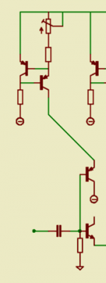
I have shown, in a previous topic in Solid State
Solid State >Offset Correction using Bias Compensation
http://www.diyaudio.com/forums/showthread.php?postid=816559#post816559
ACTIVE BIASING!
See picture below:
If is about same Current in PNP transistor, the biasing T,
as in the NPN transistor, the working T,
then
the base current of PNP will give correct bias alone.
Here is added an adjustable constant current source,
to achieve exact bias current
for nullify any currents in R-in.
/lineup copyright
Attachments
Re: Re: Re: Transistor biasing techniques
Hi Lineup,
This is a nice touch and on the face of it this will work, but all those base- and other currents are strongly temp dependent. So you may adjust the pot for a specific point but it will then drift.
The reason that these techniques are often used in IC chips is that these track in temperature and can be sized such that they track over a large temp range. But with discretes it is another kettle of fish.
Jan Didden
lineup said:I have shown, in a previous topic in Solid State
Solid State >Offset Correction using Bias Compensation
http://www.diyaudio.com/forums/showthread.php?postid=816559#post816559
ACTIVE BIASING!
See picture below:
If is about same Current in PNP transistor, the biasing T,
as in the NPN transistor, the working T,
then
the base current of PNP will give correct bias alone.
Here is added an adjustable constant current source,
to achieve exact bias current
for nullify any currents in R-in.
/lineup copyright
Hi Lineup,
This is a nice touch and on the face of it this will work, but all those base- and other currents are strongly temp dependent. So you may adjust the pot for a specific point but it will then drift.
The reason that these techniques are often used in IC chips is that these track in temperature and can be sized such that they track over a large temp range. But with discretes it is another kettle of fish.
Jan Didden
Yesss!
This is EXACTLY what I had in mind when I started this thread! Thanks guys! I will try to implement these mathematical techniques into my circuits. Keep posting! It isn't just me that will find these techniques useful, my main interest in creating this thread is to create a place one can go for reference to find some very useful biasing techniques and gain experience. As for those biasing techniques you posted, lineup, I am wondering if there is a way to compensate for ther temperature variations, maybe using complementary versions of this technique in the same circuit? That might work for amps because all the excess current of one half would flow through the other into ground... I will keep experimenting until I have found a style that suits my interest in electronics. I mainly went into this because I know that I can help others while also doing what I like to do best-use my brain! As for putting this in the everything else forum, I knew I might get some better responses in the solid state forum (not an insult in any way) but I didn't think that this was strictly related to amplifiers (maybe I was wrong, maybe I was right). Keep going!
This is EXACTLY what I had in mind when I started this thread! Thanks guys!
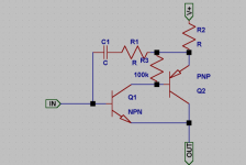
I will try to implement these mathematical techniques into my circuits. Keep posting! It isn't just me that will find these techniques useful, my main interest in creating this thread is to create a place one can go for reference to find some very useful biasing techniques and gain experience. As for those biasing techniques you posted, lineup, I am wondering if there is a way to compensate for ther temperature variations, maybe using complementary versions of this technique in the same circuit? That might work for amps because all the excess current of one half would flow through the other into ground... I will keep experimenting until I have found a style that suits my interest in electronics. I mainly went into this because I know that I can help others while also doing what I like to do best-use my brain! As for putting this in the everything else forum, I knew I might get some better responses in the solid state forum (not an insult in any way) but I didn't think that this was strictly related to amplifiers (maybe I was wrong, maybe I was right). Keep going! I have been experimenting with those biasing circuits. I have only found one problem-how do I bias Q3 and Q4? I have seen this arrangement used in many other circuits but I havent got much of an idea of how it works yet. I am assuming that since R2 has a POT in series with it, that it is supposed to be larger than R3, but I could be wrong. I am wondering if this common-emitter design is what he was thinking about:
edit: AARGH!!! (yes, it can be that frustrating) I think I found out why Q3 and Q4 had 9V potential at the base! Of course, I forgot the resistor in parallel to the supply so it was acting like huge capacitor! Hey, at least I know the problem is without running to DIYAudio, shows I'm learning something-yay!
edit: AARGH!!! (yes, it can be that frustrating) I think I found out why Q3 and Q4 had 9V potential at the base! Of course, I forgot the resistor in parallel to the supply so it was acting like huge capacitor! Hey, at least I know the problem is without running to DIYAudio, shows I'm learning something-yay!
Attachments
eergh... I hate posting four times in a row, but, moderator, can you move this thread to the solid state forum? I am sorry about putting this in the most unuseful forum, but I am quite new and I wish no hard feelings to those who have to put up with things like this. Though I believe it doesn't happen regularly, it is always good to know that your assistance is appreciated.
-Anthony
-Anthony
- Status
- This old topic is closed. If you want to reopen this topic, contact a moderator using the "Report Post" button.
- Home
- Amplifiers
- Solid State
- Transistor biasing techniques