Is this circuit a good substitute for opamp based buffers in active crossovers?
I´m going to build a 90Hz 12dB crossover fo a biamp setup and discrete buffers would "feel" better than ICs.
This article ( http://www.tkhifi.com/div/Erno_Borbely_fet_articel_2.pdf#search="Jfet white follower" )
mentions an output impedance of 2,3 ohms, but also that the input capacitance is high enough to cause trouble in filter applications. Should I be worried about that?
Attachments
.
Hello Fuling
no takes care to the input capacitance of the 2SK170 J-Fet:
the parasitic capacitance of the PCB tracks is higher than J-Fet.
For a crossover frequency of 90 Hz you must not have problems whit adequate resistors value(not more high than 20-30 K Ohms).
I agree with you for discrete output buffer .
Thanks.
Perhaps this (http://www.diyaudio.com/forums/showthread.php?threadid=70745&highlight="Jfet+buffer") would be even better, assuming we change to a bipolar supply?
Perhaps this (http://www.diyaudio.com/forums/showthread.php?threadid=70745&highlight="Jfet+buffer") would be even better, assuming we change to a bipolar supply?
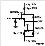
Fuling, very good buffer. This is a fet derived 'White follower' developed in the '30'A or 40's for tubes.
One small addition can make this design almost perfect. Just add an other 22 ohm resistor between the OUTPUT source follower and the DRAIN of the lower fet. This will give you virtually ZERO DC offset from input to output, allowing you to DIRECT COUPLE. This is very important, as good caps are more expensive and space consuming than good fets. This change PRESUMES the matching of the two output fets. If you do not or can not match the fets, then put a trim pot or resistor in series or parallel to the bottom 22 ohm resistor and change its value to 10 ohms or so. Then you can adjust for ZERO DC OFFSET.
One small addition can make this design almost perfect. Just add an other 22 ohm resistor between the OUTPUT source follower and the DRAIN of the lower fet. This will give you virtually ZERO DC offset from input to output, allowing you to DIRECT COUPLE. This is very important, as good caps are more expensive and space consuming than good fets. This change PRESUMES the matching of the two output fets. If you do not or can not match the fets, then put a trim pot or resistor in series or parallel to the bottom 22 ohm resistor and change its value to 10 ohms or so. Then you can adjust for ZERO DC OFFSET.
This is one of the projects I'm working on also in time-sharing mode. Since my preamp is all single-ended JFET class A, it didn't make sense to me to give up and use opamps for the crossover.... My first effort uses simple JFET buffers with current source loading. I may try something more sophisticated when the rest of my projects cool down a bit.
Dear All,
I have always believed that the complementary fet follower was “better” than the White fet follower. I now believe that this last circuit is better suited for a Xover because we are working with source and load impedance in the 5-20 K Ohm range and that, with these values, the main contribution to the distortion should be caused by the nonlinearity induced by the input capacitance. The zero offset mod suggested by John Curl might well be another reason to choose this circuit.
Now, all this reasoning is based on simulation data, can someone with “real world” knowledge comment?
In advance I thank you.
Philippe.
Ps I know “simple circuits go and test for yourself” …
The art of linear electronics / John Linsley Hood , 1998
The above is an outstanding book which analyzes the historical
development of gain modules, from just feedback via the common element
on a transistor, to two stage feedback, to three stage feedback.
Finally you get to a modern OP AMP circuit.
The question arrises of when is it better to use a JFET input instead
of a BJT input.
As I know, the justification would be the expectation of lower noise or lower distortion.
Of course one can do simulations, but those tend only to confirm what you have decided to set up. To understand the trade offs, one really needs to do analysis.
Noise is a function of the impedance the device is connected to. When this is a low impedance, like the output from another opamp like circuit, a BJT will give lower noise.
Other low impedances are low impedance microphones, and moving coil phone cartridges.
When you have a high impedance, like a moving magnet phone cartridge, I believe the JFET can give less noise.
To Be Continued, pertaining to distortion.
Some types of open ended topics will do better if a parallel discussion is held here:
Audio Explorations:
http://groups.google.com/group/audioex_amps_atob
http://groups.google.com/group/audioex_power_supplies
http://groups.google.com/group/audioex_thermal_mechanical
I've just opened up a thread for this. Just make sure you are registered with Google, then join this group, and start posting.
http://groups.google.com/group/audioex_amps_atob/browse_thread/thread/63d70b698ba97db6
zenmasterbrian said:The question arrises of when is it better to use a JFET input instead
of a BJT input.
Or when it makes sense to use a triode -- the most liear amplification device yet devised by mankind.
dave
PS:
If anyone wants to talk about the use of JFETs, in a broader context, these are excellent places:
http://www.diyaudio.com/forums/showthread.php?s=&postid=1016880#post1016880
And at audio explorations
http://groups.google.com/group/audioex_preamp_source/browse_thread/thread/844f6608b617ae28?hl=en
If anyone wants to talk about the use of JFETs, in a broader context, these are excellent places:
http://www.diyaudio.com/forums/showthread.php?s=&postid=1016880#post1016880
And at audio explorations
http://groups.google.com/group/audioex_preamp_source/browse_thread/thread/844f6608b617ae28?hl=en
zenmasterbrian said:PS:
If anyone wants to talk about the use of JFETs, in a broader context, these are excellent places:
http://www.diyaudio.com/forums/showthread.php?s=&postid=1016880#post1016880
And at audio explorations
http://groups.google.com/group/audioex_preamp_source/browse_thread/thread/844f6608b617ae28?hl=en
ZMB,
Why do you always want us to go somewhere else?? We ARE talking about jfets, right here! Just put in your 2cts worth!
Jan Didden
planet10 said:
Or when it makes sense to use a triode -- the most liear amplification device yet devised by mankind.
dave
That's why I use my marchand XM-126 for all crossover duties
") Expensive toy, but always does what you tell it to, without noise or other problems, and you can quickly and easily change out the XO boards.
Expensive toy, but always does what you tell it to, without noise or other problems, and you can quickly and easily change out the XO boards.I would question that notion of Triodes being linear. Or of pentodes, or of JFETs.
Maybe triodes are more linear, in their charcteristic curves, more so than BJTs. But we need to look at the entire circuit.
I'm not against tubes. I learned electronics with tube radios, HiFi's, and TV's.
I've built tube amps. I see the stuff sold in the Hi-End magazines today.
I posted on this thread because I think there is something to be considered about using JFET inputs.
But what actually determines the distortion of a gain block?
Most basic gain circuits are self biasing, with a common element resistor. So a common cathode triode circuit has a cathode resistor. Same goes for solid state circuits.
Unless this is bypassed, that resistor, in relation to the load resistor, will largely determine the gain, and radically reduce the distortion. The circuit is linearized.
Most modern circuits are of the op-amp type, and are designed for much much lower distortion levels. Most of the distortion is only that of the front end, and only in how it works relative to a differential signal.
The key to lowering distortion is lowering the current variation. This means using stiffer current sources.
Then, there is the issue of large signal swing and the common mode voltage.
This, the non-inverting mode, is when you are inclined to have the highest distortion, though even that is not much.
Some monolithic op amps use very sophisticated ways of compenating for this.
The most important thing for keeping distortion down is limiting current swing in the input diffpair. This is done by using stiffer current sources, but also by getting the highest gain possible in all stages, so that 2nd stage loading of the first stage is minimized.
Not all distortions are equal. Some designs can favor even order distortions over odd order.
Some discrete circuits use diffpair mirroring. That is, they use a second complementary diffpair, so that as the common mode voltage moves, you get a symetrical effect.
I posted on this thread because there is the question of using JFET inputs to get a square law distortion.
But is it really this simple? When you look at the entire circuit, does that aspect of the input transistor characteristic curves really reflect in the output in that way?
Douglas Self and G. Randy Sloan write about this, and largely reject it.
I have a thread specifically for dealing with the lowest obtainable distortion:
http://groups.google.com/group/audi...26d9c/9801c11d6fad8c4b?hl=en#9801c11d6fad8c4b
Here the possiblitity of using higher voltage rails on the first stage of the circuit, to get lower distortion when used in non-inverting mode, is opened:
http://groups.google.com/group/audioex_preamp_source/browse_thread/thread/844f6608b617ae28?hl=en
- Status
- This old topic is closed. If you want to reopen this topic, contact a moderator using the "Report Post" button.
- Home
- Amplifiers
- Solid State
- Active crossover with Jfet buffers?