Hello everyone.
Now I'm planning to build this circuit.
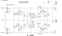
Please see the schematic on the bottom of the paper.
[LT1028A on the schematic is just an example]
And this paper recommends to use NE5534 as the opamps.
I'm going to supply +-16v to input and get +-15v DC
And I'm searching for some opamp with low-distortion and low-noise, working well in this circuit.
Though it's easy to put AD8065 or AD8610 thoughtlessly and forget about that, but I'm just wondering which one will be better.
Any suggestion is welcomed !!
Thank you for reading.
okina
Now I'm planning to build this circuit.
Please see the schematic on the bottom of the paper.
[LT1028A on the schematic is just an example]
And this paper recommends to use NE5534 as the opamps.
I'm going to supply +-16v to input and get +-15v DC
And I'm searching for some opamp with low-distortion and low-noise, working well in this circuit.
Though it's easy to put AD8065 or AD8610 thoughtlessly and forget about that, but I'm just wondering which one will be better.
Any suggestion is welcomed !!
Thank you for reading.
okina
Attachments
Hi okina
For DC operations is not very important distortion and speed of the circuit.
Other performances you must try ,like offset and DC stability.
The LT1028 and 1128 are one of the best OP amp for your very low noise,speed,stability and distortion in the market.Their features are so much for this circuit.
A simple OP 07 is a good and adequate solution for your DC power supply.
The NE5534 will go less well.
Hi okina,
That circuit is a variant (high current) of Walt Jung SupeRegulator and needs same tweaking, I think.
Voltage reference TL431 should be powered from regulated side, preferable with CCS, but not necesary, and could be even better filtered
R3(4) should be = parallel resistance of R12+R14 (R11+R13)
No remote sensing network as in SupeRegulator.
Everything you will ever want is here:
http://waltjung.org/Regs.html
Re: Hi okina
Thank you, Parsecaudio and aparatusonitus. ;D
So, LT1028 and LT1128 will fit this circuit.
I'll try them.
>R3(4) should be = parallel resistance of R12+R14 (R11+R13)
for example, in this schematic
If R12 = 1.5k and R14 = 7.5k,
then (7.5+1.5)/1.5 = 6 ohm ?
I'm not sure what you mean.
Can you explain a bit more ?
And I can't understand "powered from regulated side".
Is there any example of that ?
If I can modify the circuit I'll try, but I already got the board and I guess I can't modify it on a large scale.
That's why I though that opamps and transistors are the main parts which I could modify.
Thank you for your suggestions anyway. ;D
Thank you, Parsecaudio and aparatusonitus. ;D
parsecaudio said:For DC operations is not very important distortion and speed of the circuit.
Other performances you must try ,like offset and DC stability.
The LT1028 and 1128 are one of the best OP amp for your very low noise,speed,stability and distortion in the market.Their features are so much for this circuit.
A simple OP 07 is a good and adequate solution for your DC power supply.
The NE5534 will go less well.
So, LT1028 and LT1128 will fit this circuit.
I'll try them.
aparatusonitus said:Hi okina,
That circuit is a variant (high current) of Walt Jung SupeRegulator and needs same tweaking, I think.
Voltage reference TL431 should be powered from regulated side, preferable with CCS, but not necesary, and could be even better filtered
R3(4) should be = parallel resistance of R12+R14 (R11+R13)
No remote sensing network as in SupeRegulator.
Everything you will ever want is here:
http://waltjung.org/Regs.html
>R3(4) should be = parallel resistance of R12+R14 (R11+R13)
for example, in this schematic
If R12 = 1.5k and R14 = 7.5k,
then (7.5+1.5)/1.5 = 6 ohm ?
I'm not sure what you mean.
Can you explain a bit more ?
And I can't understand "powered from regulated side".
Is there any example of that ?
If I can modify the circuit I'll try, but I already got the board and I guess I can't modify it on a large scale.
That's why I though that opamps and transistors are the main parts which I could modify.
Thank you for your suggestions anyway. ;D
.
Hi okina
R3(R4) is only in order to separate and filtering the output of the TL431 regulator.Your value is not critical.
The suggestion by aparatusonitus to connect the input of this regulators whit a Constant Current Reguator it's right.
Powered from regulated side it means that the resistors R2 must be connected on the regulator output(after the emitter of Q2) and R1 must to be connected after the emitter of Q1.
For the parallel calculations we have
R12 x R14 : (R12 + R14).
Whit value of 7.5 K and 1.5 K we have
7.5 x 1.5 : (7.5+1.5) as results 1.25 K Ohm and not 6 Ohm .
For the OP amp I suggest OP07 because it is sure that it works.
Re: .
Thank you again for kind explainations.
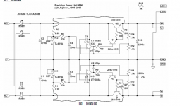
I drew and am reattaching what I understood.
But, still I'm not sure what is Constant Current Reguator.
Where should I connect the collectors of Q1 and Q2 ?
Is The TL431A on the schematic the "Constant Current Regulator" ?
About the parallel calculations, the wrong formula came to my mind.
Thank you for correcting my wrong.
Thank you again for kind explainations.
parsecaudio said:Hi okina
R3(R4) is only in order to separate and filtering the output of the TL431 regulator.Your value is not critical.
The suggestion by aparatusonitus to connect the input of this regulators whit a Constant Current Reguator it's right.
Powered from regulated side it means that the resistors R2 must be connected on the regulator output(after the emitter of Q2) and R1 must to be connected after the emitter of Q1.
For the parallel calculations we have
R12 x R14 : (R12 + R14).
Whit value of 7.5 K and 1.5 K we have
7.5 x 1.5 : (7.5+1.5) as results 1.25 K Ohm and not 6 Ohm .
For the OP amp I suggest OP07 because it is sure that it works.
I drew and am reattaching what I understood.
But, still I'm not sure what is Constant Current Reguator.
Where should I connect the collectors of Q1 and Q2 ?
Is The TL431A on the schematic the "Constant Current Regulator" ?
About the parallel calculations, the wrong formula came to my mind.
Thank you for correcting my wrong.
Attachments
Hi okina,
CCS means constant current source, but as I have allready stated, is not so important in your circuit, as resistors R1/2 are connected now to regulated side. You want to establish the same current thru TL431, so you should drop a value for R1/2 for something like 2k, becouse they now "see" less voltage.
Value of resistors R3/4 is important, becouse we want inverted and noniverted input of an error opamp to "see" the same impedance on both input, so put a 1k25 resistor for R3/4. Now, replace C3/4 with two series connected 220uF capacitors, place a 10k resistors from TL431 catodes to capacitors junction, and place a 0.1-1uF film capacitor in parallel with each TL431. Now we have the basics right and voltage reference filtered.
For error opamp OP07 is usable, but you will get much better performance with NE5534 or OP27 as chip and wery good starting point.
Hi aparatusonitus
sorry for my mistake.
The value of R3 and R4 must be the same of the parallel of R12-R14 and R11-R13.
Neglect this a unbalancing in the output will be made.
I'm not sure that in DC applications the NE5534 are better than OP07 for offset,DC stability over temperature and circuit stability.
Best are the Linear LT1028,this is a direct substitution of the two op amps NE and OP,but with higher costs.
")
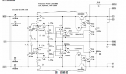
Hello, aparatusonitus
I owe you a lot for many suggestions.
If I got your suggestions right, I'd wire them rightly.
Could I get well ?
And I think I can modify them on the boards.
So, I'm going to compare the two version and confirm the effect.
Anyway, thanks alot.
I owe you a lot for many suggestions.
aparatusonitus said:Hi okina,
CCS means constant current source, but as I have allready stated, is not so important in your circuit, as resistors R1/2 are connected now to regulated side. You want to establish the same current thru TL431, so you should drop a value for R1/2 for something like 2k, becouse they now "see" less voltage.
Value of resistors R3/4 is important, becouse we want inverted and noniverted input of an error opamp to "see" the same impedance on both input, so put a 1k25 resistor for R3/4. Now, replace C3/4 with two series connected 220uF capacitors, place a 10k resistors from TL431 catodes to capacitors junction, and place a 0.1-1uF film capacitor in parallel with each TL431. Now we have the basics right and voltage reference filtered.
For error opamp OP07 is usable, but you will get much better performance with NE5534 or OP27 as chip and wery good starting point.
If I got your suggestions right, I'd wire them rightly.
Could I get well ?
And I think I can modify them on the boards.
So, I'm going to compare the two version and confirm the effect.
Anyway, thanks alot.
Attachments
- Status
- This old topic is closed. If you want to reopen this topic, contact a moderator using the "Report Post" button.
- Home
- Amplifiers
- Solid State
- Any suggestion about this circuit ?