Concerning using a servo integrator to greatly reduce DC offset for a basic power amplifier:
1) When the output signal is integrated and amplified (usually by an opamp integrator circuit), where is this feedback signal normally placed? I have seen designs that put the DC feedback signal at the inverting input of the input stage (just like where the AC regular feedback goes), and I have seen designs that put the DC feedback signal at the tail supply of the input stage (I think it adjusts the bias current such that the DC offset at the output is 0). Is there a guideline or rule of thumb to use?
2) Can the DC feedback signal be applied to the VAS stage instead of the input stage? Are there negative consequencese to this?
Generally it is placed on the input side of the differential pair. This would require an inverting integrator.rtarbell said:Concerning using a servo integrator to greatly reduce DC offset for a basic power amplifier:
1) When the output signal is integrated and amplified (usually by an opamp integrator circuit), where is this feedback signal normally placed?
To place the correction signal at the feedback side of the diff pair would require a non-inverting integrator. My understanding is that the non-inverting integrator involves a few compromises, which is why a standard configuration of an inverting integrator feeding the correction signal to the base of the input side of the differential pair transistor is the norm.I have seen designs that put the DC feedback signal at the inverting input of the input stage (just like where the AC regular feedback goes), and I have seen designs that put the DC feedback signal at the tail supply of the input stage (I think it adjusts the bias current such that the DC offset at the output is 0). Is there a guideline or rule of thumb to use?
I think I remember seeing something like this, but IIRC, the correction range is rather limited. Sorry, got no examples.2) Can the DC feedback signal be applied to the VAS stage instead of the input stage? Are there negative consequencese to this?
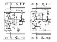
Symmetrical Dual Differential Servo
If you are building a symmetrical dual differential design you may want to experiment with these two servo options: bias adjust and feedback voltage. My experience: the bias adjust sounds more dynamic; the feedback voltage gives a slightly better DC null and will compensate for a larger DC offset.
Any better suggestions for a symmetrical dual differential servo ?
Attachments
- Status
- Not open for further replies.