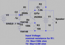
I have designed my own amp. It currently takes 100K input impedance
and I was wondering if this was pretty good for a second design attempt. I don't really know all the widely used imedances or 'standards' so if you want to give me a list that I can write down or something like that, please do. I was making this on my simulator so if something isn't quite right please tell me. You can't crank the gain up very high or else since the transistor isn't biased exactly the negative portion of the wave will start to do wierd things. The diodes are what biases the transistor, so if I could get some more diod models maybe I could find some better ones. I have commented the nominal resistances to keep the distortion under control on the schematic. Here it is:
and I was wondering if this was pretty good for a second design attempt. I don't really know all the widely used imedances or 'standards' so if you want to give me a list that I can write down or something like that, please do. I was making this on my simulator
so if something isn't quite right please tell me. You can't crank the gain up very high or else since the transistor isn't biased exactly the negative portion of the wave will start to do wierd things. The diodes are what biases the transistor, so if I could get some more diod models maybe I could find some better ones. I have commented the nominal resistances to keep the distortion under control on the schematic. Here it is:Attachments
hmm...
oops... I have seen common-emitter circuits and their simplicity doesn't appeal to me... Though I guess that for small-signal amplification they would work with minimal distortion. What I don't like about one-transistor arrangements is that you have to bias them perfectly if you want good sound which usually will take some component count if you want to use it for something other than small signal (at least with my transistors, which are low-end which I have to cope with ). I like symmetrical arrangements like symasm4 or the 4QD-TEC one here: http://www.4qdtec.com/pwramp.html. This one is cool because it uses a self-biasing chain. If I sound like a complete idiot who doesn't have any experience, please let me know. Also, I have been trying to develope another amplifier based on the 4QD-TEC one and I was wondering, don't amplifiers that float good have more of a tendancy to oscillate? Meaning that the speakers will scream at you from larger distances away when your holding a mic? I know about positive and negative feedback, are there any good ways that I can suppress oscillation without affecting the circuit's behavour majorly? I like straigt-forward designs that don't add any "flavour" to the sound so that I can apply my own effects. If you have any good, simple amplifier schematics that you think I will like, please post. Gosh... I need to learn how to make stuff that works
  ...
...
BTW, is this circuit useful for anything except for absolutely nothing?
oops... I have seen common-emitter circuits and their simplicity doesn't appeal to me... Though I guess that for small-signal amplification they would work with minimal distortion. What I don't like about one-transistor arrangements is that you have to bias them perfectly if you want good sound which usually will take some component count if you want to use it for something other than small signal (at least with my transistors, which are low-end which I have to cope with
). I like symmetrical arrangements like symasm4 or the 4QD-TEC one here: http://www.4qdtec.com/pwramp.html. This one is cool because it uses a self-biasing chain. If I sound like a complete idiot who doesn't have any experience, please let me know. Also, I have been trying to develope another amplifier based on the 4QD-TEC one and I was wondering, don't amplifiers that float good have more of a tendancy to oscillate? Meaning that the speakers will scream at you from larger distances away when your holding a mic? I know about positive and negative feedback, are there any good ways that I can suppress oscillation without affecting the circuit's behavour majorly? I like straigt-forward designs that don't add any "flavour" to the sound so that I can apply my own effects. If you have any good, simple amplifier schematics that you think I will like, please post. Gosh... I need to learn how to make stuff that works ...BTW, is this circuit useful for anything except for absolutely nothing?
I assumed you wanted a single transistor stage, like the one you posted. The circuit will produce sound, but not very well.
What exactly are you wanting to amplify, and what load are you wanting to drive?
These two pages make a spectacular introduction to amplifier design.
http://sound.westhost.com/amp-basics.htm
http://sound.westhost.com/amp_design.htm
P.S. You schematic is a common-emitter amp, just with a... unusual bias generator.
hmm...
oops... I have seen common-emitter circuits and their simplicity doesn't appeal to me... Though I guess that for small-signal amplification they would work with minimal distortion. What I don't like about one-transistor arrangements is that you have to bias them perfectly if you want good sound which usually will take some component count if you want to use it for something other than small signal (at least with my transistors, which are low-end which I have to cope with ). I like symmetrical arrangements like symasm4 or the 4QD-TEC one here: http://www.4qdtec.com/pwramp.html. This one is cool because it uses a self-biasing chain. If I sound like a complete idiot who doesn't have any experience, please let me know. Also, I have been trying to develope another amplifier based on the 4QD-TEC one and I was wondering, don't amplifiers that float good have more of a tendancy to oscillate? Meaning that the speakers will scream at you from larger distances away when your holding a mic? I know about positive and negative feedback, are there any good ways that I can suppress oscillation without affecting the circuit's behavour majorly? I like straigt-forward designs that don't add any "flavour" to the sound so that I can apply my own effects. If you have any good, simple amplifier schematics that you think I will like, please post. Gosh... I need to learn how to make stuff that works ...
BTW, is this circuit useful for anything except for absolutely nothing?
oops... I have seen common-emitter circuits and their simplicity doesn't appeal to me... Though I guess that for small-signal amplification they would work with minimal distortion. What I don't like about one-transistor arrangements is that you have to bias them perfectly if you want good sound which usually will take some component count if you want to use it for something other than small signal (at least with my transistors, which are low-end which I have to cope with
). I like symmetrical arrangements like symasm4 or the 4QD-TEC one here: http://www.4qdtec.com/pwramp.html. This one is cool because it uses a self-biasing chain. If I sound like a complete idiot who doesn't have any experience, please let me know. Also, I have been trying to develope another amplifier based on the 4QD-TEC one and I was wondering, don't amplifiers that float good have more of a tendancy to oscillate? Meaning that the speakers will scream at you from larger distances away when your holding a mic? I know about positive and negative feedback, are there any good ways that I can suppress oscillation without affecting the circuit's behavour majorly? I like straigt-forward designs that don't add any "flavour" to the sound so that I can apply my own effects. If you have any good, simple amplifier schematics that you think I will like, please post. Gosh... I need to learn how to make stuff that works ...BTW, is this circuit useful for anything except for absolutely nothing?
You posted before I posted that last post... As for the load, I was thinking on trying to drive an 8-ohm to test it and when I knew it was safe try it as a preamp maybe. I am trying to amplify my microphone so I can have some louder sound (so that I don't have to amplify it digitally which is a pain). I got the "unusual bias generator" from the 4QD-TEC schematics, it seemed like an easy way to bias low-requirement circuits and if your good enough maybe make something better. This appeals to me because, unlike a resistor, the bias will fluctuate less when the supply voltage changes. This is why the 4QD schematic can work over a large supply range.
That part of the 4QD-TEC schematic is a constant current source, it's designed to source (technically sink in this case, but who cares ) a constant current regardless of the voltage on the collector, it's not designed as a bias circuit for any kind of linear voltage amplifer.
Voltage divider biasing does give pretty poor PSRR, but automatically adjusts bias to the best level.
) a constant current regardless of the voltage on the collector, it's not designed as a bias circuit for any kind of linear voltage amplifer.Voltage divider biasing does give pretty poor PSRR, but automatically adjusts bias to the best level.
keantoken,
This amplifier can't possibly work. The output impedance is way too high; the output coupling cap is way too small; etc. In addition, the biasing is very questionable. There is no way you will get any appreciable power into the load.
Low output impedance is one of the reasons most power amps use emitter (or source) followers. Your amp might work if you use emitter followers, and if it is biased properly.
I don't wish to be negative, but you asked for comments.
Rick
I really like the 4QD design, Do you think there is any way to improve it
with modern transistors and such? I have been messing around with this on my simulator but I don't have enough models to be able to find anything out. Although probably best left to more experienced people, I want in on this if the challenge is taken up. Whatcha think?
with modern transistors and such? I have been messing around with this on my simulator but I don't have enough models to be able to find anything out. Although probably best left to more experienced people, I want in on this if the challenge is taken up. Whatcha think?
I have made a revision of the 4QD circuit that is probably like the last one in useability but it seems to work better with higher input voltages and with less distortion.
I have been tuning this one on my simulator
 . And I have tried to keep the resistor values at easy-to-find values, though I'm not sure about R4 and R5. If you think it won't work, please tell me of any ways to make it work! I know I can attract a lot of sarcastic comments sometimes but if you have anything that would help my intellectual developement, please let me know. That is all I have to say, heres the schematic:
I have been tuning this one on my simulator
. And I have tried to keep the resistor values at easy-to-find values, though I'm not sure about R4 and R5. If you think it won't work, please tell me of any ways to make it work! I know I can attract a lot of sarcastic comments sometimes but if you have anything that would help my intellectual developement, please let me know. That is all I have to say, heres the schematic:Attachments
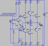
I think this concept that I have yet to grasp is the problem (as in, I don't get the problem, not why my circuit is so horrible) that makes my first circuit so horrible: what defines the output impedance? Is it R3 (I know what defines the input resistance)? I believe that bipolar transistors have some impedance but from the circuits I have seen I think others believe it as insignificant .
If some of the transistors are overdriven, keep in mind that I hadn't finished testing for that when I posted this.
. If some of the transistors are overdriven, keep in mind that I hadn't finished testing for that when I posted this.
one more thing-
Ok, hopefully I'll get a response from this one...
I have decided to use the current limiting technique from the 4QD circuit: if the output transistors are being overdriven, you can connect a resistor between the collector of Q4 and the collector of Q3 which causes the gain to go down but will protect the circuit if something explodes. do the same thing on the other half of the circuit. if the overdriving is in an earlier stage, you can put a resistor between the collector of Q2 and the collector of Q1 and the same with the complementary half of the circuit.
Also, I just realized from another thread that running DC through the input device isn't a good idea, so if you want to be safe, like me, then I would suggest fitting a capacitor just after the input.
I haven't really done a lot of testing on the current limiting, but it seems that it doesn't really help much if your input is too high... if this is actually the case, then I think I will try to implement current limiting ( or voltage limiting) on the input transistors. This shouldn't be too hard, but, once again, I will ask for comments.
If still noone continues to post, I will consider this thread as dead... Usually being ignorant is the last thing on my mind, but it sometimes happens anyways! please don't be annoyed if that's the problem.
Remember, I am only 13!
Also: the output seems to become off center at lower frequencies (the wave peaks aren't the same hight). I believe this is because of a slight imperfection in R1 and may also be because of C4, I want this to be a low-distortion amp and I was wondering about other values for C4 if that's the problem.
I'm sorry to say, there are still numerous problems with biasing, not to mention major topological problems.
Look at the input pair, a change in differential input voltage will cause a change in current in the pair, when current goes up it will pull the bases of Q3 and Q5 together, causing the bases of Q2 and Q6 to be pulled apart, causing the bases of Q4 and Q7 to be pulled together. In other words, input signal modulates output stage bias, but does not (directly) effect output voltage, this topology cannot effectively amplify.
Have you read the links I posted?
I have opened the links but I don't have much time to read them. Is there any way to isolate the bases of Q3 and Q5? Would using a capacitor work? I was hoping for more suggestions. it's okay to come out and say that it's unimprovable. I thought that it might not be amplifying worth it's potential when I used the simulator. I need advice from real people as to where my designs should be going and how I can improve them. To me, this is the best way of learning-feedback. I acknowledge that some reading material is essential and I will do my best to find time to look at those links but until I get some more useful advice (not a intended as a hurtful comment), I can't really know where to go and how to make my designs worth the money. I don't intend to be ignorant, as I said before. I don't have a good source of components, which is why my simulator is the only way I can try to design something. *sigh*
is the only way I can try to design something. *sigh*Amp design
Hello Keantoken
Your schematic have some errors.The first one that I see is for Q1: with a coupling capacitor (C1) the base of this transistor is floating and not well biased.Moreover the gain of the output transistor is not sufficient to drive a 8 Ohm load.The output impedance is determined nearly entire by the current gain of Q4 and Q7.
A little suggestion to you:why not tests with some more traditional circuit,in order to only make some experience?
The first thing you should do is mentally trace through your schematic to make sure an input signal produces a change in output voltage, and that a positive signal into the feedback node produces a negative output. Try to follow what I did analyzing your circuit in my last post.
Don't simulate for this, just do it mentally, a CE inverts, treat it as a gain of -1 for the sake of this analysis, an EF simply follows (gain of 1).
Give up on capacitors until you have a better grasp of biasing, they're not necassary for biasing and simply complicate things.
Design with a voltage source that is grounded on one end.
P.S. To follow these last two tips you'll need to design around a dual supply (V+ Gnd V-).
I say don't build anything, keep simulating, it's a great way to learn.
Thirteen eh? You're doing well for your age and have plenty of time to catch up to people on this forum. I knew no more than you do when I was thirteen, and now at seventeen I think I can call myself a competent designer.
Ok, I can do that. Do all amplifiers have to invert? Is this how you get good AC feedback? I think my biggest problem is biasing transistors, my simulator works no matter how I bias them! I don't waste time trying to simulate just to find out if my amplifier inverts, I do the best not to simulate until I have something worth simulating. I will keep trying to design my own, but I think I will go with the symasm4. Though I will have to see if I can find some alternate transistors so that I can find them. I will try to find time to read through those links. Thanks .
.All amplifiers with global feedback need an inverting input.
A voltage is measured across somthing, no node has a voltage in and of itself, it only has voltage relative to something else, it follows that all voltage input amps have two input nodes, an inverting input and a noninverting input.
Of course not all amps have a practical inverting input (in some cases it is a supply rail).
- Status
- This old topic is closed. If you want to reopen this topic, contact a moderator using the "Report Post" button.
- Home
- Amplifiers
- Solid State
- feedback on my design