Okay, I know this topic has been discussed before, and I know that in the end, the basic Vbe multiplier comes out on top over a thermistor for voltage regulation as a function of temperature.
I don't *think* this idea has been discussed in other threads:
Why not use a thermistor inside of the Vbe multiplier?
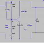
==> Let us say we have your basic NPN multiplier with R1 on top (base to collector) and R2 on the bottom (base to emitter). How about replacing either one with a thermistor for sharper response, and then have the thermistor itself (as opposed to the transistor) mounted on the heatsink?
If you have a positive tempco thermistor (resistance increases with temp), then use it to replace R2 (the thermistor gets hotter, so R2 increases, thus reducing the 1 + R1/R2 product). If you have a negative tempco thermistor, use it to replace R1 (same reasoning as above).
I read in Douglas Self's book a method to increase the tempco of the basic Vbe multiplier (so I am assuming that a higher tempco is better than a lower tempco). I figured with this method, the tempco of the overall Vbe multiplier is a factor of the B constant (which can be made very high, depending upon the thermistor used).
Ideas? Am I off my rocker?
I don't *think* this idea has been discussed in other threads:
Why not use a thermistor inside of the Vbe multiplier?
==> Let us say we have your basic NPN multiplier with R1 on top (base to collector) and R2 on the bottom (base to emitter). How about replacing either one with a thermistor for sharper response, and then have the thermistor itself (as opposed to the transistor) mounted on the heatsink?
If you have a positive tempco thermistor (resistance increases with temp), then use it to replace R2 (the thermistor gets hotter, so R2 increases, thus reducing the 1 + R1/R2 product). If you have a negative tempco thermistor, use it to replace R1 (same reasoning as above).
I read in Douglas Self's book a method to increase the tempco of the basic Vbe multiplier (so I am assuming that a higher tempco is better than a lower tempco). I figured with this method, the tempco of the overall Vbe multiplier is a factor of the B constant (which can be made very high, depending upon the thermistor used).
Ideas? Am I off my rocker?
Hi,
if you select a high value thermistor and use it in parallel to one of your resistors then you can get partial compensation.
You may be able to trim the thermistor effect by adding another resistor in series.
A pot here might allow you to investigate the tempco.
I think a thermistor on it's own will vary far too much, even a low value NTC varies more than 10:1 over quite a small range of temp from ambient.
Have you tried putting a thermistor bridge on the inputs to an opamp and measure what happens? just putting your hand near absorbs heat radiation and blowing gently puts the output meter offscale.
I have done this myself on Three differant amps with satisfactory results !
You still have to be carefull where you place the thermistor for optimum tracking !
You can easily overcompensate and end up with the bias going down when the output devices warm up. Sometimes I wonder if we are biasing correctly anyway as the heat has to come out of the device before we compensate. I believe that there are devices out there that have a temperature tracking diode on the die of the output device. Bet that would track well!
regards Trev
I once designed a power supply that used the LM318K steel regulator chip . This required a very tight voltage of 36 volts and despite the perceived claims found that the output varied by about 0.5 volt over a temperature range of 10-30 deg using the design sheet schematics, however by using a neg value thermistor (10k @ 20c ) in parrallell with a I think 470 resistor I managed to bring the variation down to about 25 my . Over a 100 units were produced and used with very good results!!
I say this not as a boast, but as encouragement to others as this is a valid compensation technique!
However there is and always will be time lag re the compensation and prefer to attempt to design out drift in the first place
Regards trev
I say this not as a boast, but as encouragement to others as this is a valid compensation technique!
However there is and always will be time lag re the compensation and prefer to attempt to design out drift in the first place
Regards trev
You are dead right ! That Is why I used the term perceived
the specifiers can be very deviouse and know that the die will self heat and move the ref source on the chip !!!
I was in trouble on that project untill I came up with the thermistor compensation. But to be Honest I had seen thermistors used by Leak and also Trio / kenwood in some of their older amps. Clever these old boys when you think what they had to work with !
Regards Trev
") .
.Hi Tim,
I used a pair of NTC resistors touching the zener, in the sensing network. In this particular case, reducing the ambient temperature helped a lot. The zener was being fed by a CCS. I did try a string of 27 V zeners and ended up with exactly the same drift. Same for some 33V and 47 V units.
-Chris
I used a pair of NTC resistors touching the zener, in the sensing network. In this particular case, reducing the ambient temperature helped a lot. The zener was being fed by a CCS. I did try a string of 27 V zeners and ended up with exactly the same drift. Same for some 33V and 47 V units.
-Chris
Avalanche breakdown and Zener breakdown have opposite (but not equal) tempcos. At higher breakdowns the avalanche effect dominates and you get a severely positive tempco. at very low voltages zener dominates and you get a mild negative tempco.
Right around 5.6v the to effects cancel and give a near zero tempco.
It doesn't suprise me that 27v zeners didn't work, by that point tempco is largely dominated by avalanche.
Either way, it sounds like your solution worked just fine.
Take a look at this datasheet to see what I mean.
http://www.fairchildsemi.com/ds/BZ/BZX79C5V6.pdf
Edit: Oops, maybe it's 5.2v not 5.6v?
Trev,
Could this be an example of what you're looking for?
www.passlabs.com/np/stasis2-3schem.tif
Cheers,
Graeme
Could this be an example of what you're looking for?
www.passlabs.com/np/stasis2-3schem.tif
Cheers,
Graeme
Hi Tim,
I am fully aware of that, but thanks. I can not imagine a string of 5.1 V diodes across the PCB. I had a board size to work within as well, and a price point. Welcome to the world of engineering.
For an audio voltage regulator, staying at one voltage isn't that important. A slow drift of a couple volts at 285 VDC will not bother anything. Drifting from 274 V to 294 V (no compensation) just bugged me. Now it goes from 282 V to 284.5 VDC. I can live with that. Most of the drift is due to ambient temperatures inside the case rising.
My experiment with varying values of diode voltage was just to see if the temperature co-effecient varies with voltage drop. If it does, it's not enough to matter.
-Chris
- Status
- This old topic is closed. If you want to reopen this topic, contact a moderator using the "Report Post" button.
- Home
- Amplifiers
- Solid State
- Vbe mult + thermistor