Hi Zeus
Try a forum search on Zobel network. It is discussed extensivly.
http://users.ece.gatech.edu/~mleach/ece4445/downloads/zobel.pdf
")
Try a forum search on Zobel network. It is discussed extensivly.
http://users.ece.gatech.edu/~mleach/ece4445/downloads/zobel.pdf
simulation transient analysis
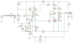
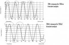
Well the inductor in series helped solved mostly but not completely the problem. Shortcircuited in parallel with a 10R resistor is worse. I'll try the 1uF from output to ground. But still my main problem is distortion i am seeing in the simulation. Anyone has any idea where its coming from? Simulation o/p attached for 20Hz and 20KHz signals.
Well the inductor in series helped solved mostly but not completely the problem. Shortcircuited in parallel with a 10R resistor is worse. I'll try the 1uF from output to ground. But still my main problem is distortion i am seeing in the simulation. Anyone has any idea where its coming from? Simulation o/p attached for 20Hz and 20KHz signals.
Attachments
I would have expected to see some rail decouplers at the series resistor to the vas stage about 100 uf!
Also at a glance the diff pair looks like it ill be unbalanced r3 should be around 1 k r3 should be aprox two times the value of the constant current tail resistor with that type of CCS
Also i can not see to clearly but it looks like rail clipping with rail sag combined ie the droops between rectifier charging pulses on the psu
Regards Trev
Re: simulation transient analysis
Hello Zeus,
for me looks like that your timestep is far too big.
Perhaps You use automatically generated timesteps :
switch this off and use much smaller steps.
Regards
Heinz!
....... But still my main problem is distortion i am seeing in the simulation. Anyone has any idea where its coming from? Simulation o/p attached for 20Hz and 20KHz signals. [/B]
Hello Zeus,
for me looks like that your timestep is far too big.
Perhaps You use automatically generated timesteps :
switch this off and use much smaller steps.
Regards
Heinz!
Better simulation results
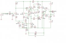
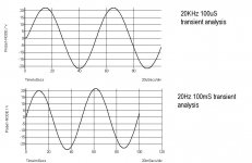
I modified the amp with values shown. I'll post the transient analysis next, but reducing the timestep to 100mS for 20Hz and 100uS for 20KHz did not show any distortion. Is this reliable? I mean not for real world but at least for the simulation?
Thanks
I modified the amp with values shown. I'll post the transient analysis next, but reducing the timestep to 100mS for 20Hz and 100uS for 20KHz did not show any distortion. Is this reliable? I mean not for real world but at least for the simulation?
Thanks
Attachments
The transient analysis looks better
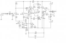
Attached are the transient analysis with reduced time steps. Increasing the timestep even with R3=1K shows distortion. Any particular reason? Am using simetrix intro could it be due to the fact that its an intro version?
Attached are the transient analysis with reduced time steps. Increasing the timestep even with R3=1K shows distortion. Any particular reason? Am using simetrix intro could it be due to the fact that its an intro version?
Attachments
Hi Zeus,
I think powerbecker has hit it with
Have you found how to do this?
R3 is still too big.
Q3 Vbe controls the current in r3. So 0.6V pushes 0.6mA through R3 (0.6/1000).
Your constant current sink is set at 2mA (0.7/330) so you are sinking 1.4mA through Q2. That makes your LTP unbalanced. That in turn increases distortion in the LTP.
You must alter some or one of your resistors to balance the currents in the LTP halves. You can monitor the currents in R1 & R2 to check balance.
I think powerbecker has hit it with
for me looks like that your timestep is far too big. Perhaps You use automatically generated timesteps :
switch this off and use much smaller steps.
Have you found how to do this?
R3 is still too big.
Q3 Vbe controls the current in r3. So 0.6V pushes 0.6mA through R3 (0.6/1000).
Your constant current sink is set at 2mA (0.7/330) so you are sinking 1.4mA through Q2. That makes your LTP unbalanced. That in turn increases distortion in the LTP.
You must alter some or one of your resistors to balance the currents in the LTP halves. You can monitor the currents in R1 & R2 to check balance.
You must reduce C5 in size, 100pF here is nearly a guarantee for stability problems. Try 10pF or 22pF at most.
The purpose of this c is to phasehift the feedback signal, but unfortunately it also decreases closed loop gain for higher freqs, increasing feedback factor. Values like 100pf here can only be used for amps that are unitygain stable.
Mike
The purpose of this c is to phasehift the feedback signal, but unfortunately it also decreases closed loop gain for higher freqs, increasing feedback factor. Values like 100pf here can only be used for amps that are unitygain stable.
Mike
AndrewT said:
R3 is still too big.
Q3 Vbe controls the current in r3. So 0.6V pushes 0.6mA through R3 (0.6/1000).
Your constant current sink is set at 2mA (0.7/330) so you are sinking 1.4mA through Q2. That makes your LTP unbalanced. That in turn increases distortion in the LTP.
You must alter some or one of your resistors to balance the currents in the LTP halves. You can monitor the currents in R1 & R2 to check balance.
oopps I miscalculated post 13, I didn't take into account it is a simulator. Real small signal BJT's Vbe is usually around 0.6V.
(1.4/330)/2=2.12mA 0.7/2.12=330R...not counting base current of Q3. Having 2 diode drops on the CCS of the LTP, makes R3 equal in value to R16 since the current is divided equally as Andrew stated. Each transistor needs to have equal heat dissapation or drift will occur (well in the real world it will
 )
)- Status
- This old topic is closed. If you want to reopen this topic, contact a moderator using the "Report Post" button.
- Home
- Amplifiers
- Solid State
- Amp distortion