Hi Glen!
The cap on the base of Q401 (C401) is supposed to delay the closing of the relays on power up, but there is no provision to open the relays on power down. The circuit has to bleed out for the relays to open.
The relay circuit is pretty simplistic, and SAE should have done it better. All you can do make sure that the offset adjust is as close to zero as possible so that when the contacts open and close the offset is as low as possible (with the .1µf caps across the relay contacts, seems SAE knew that thump might be a problem, but did nothing to address it).
The amp doesn't have a lot of caps...replace them with modern equivalents. Should be able to get it done with less than $15 worth of caps.
burnedfingers said:I have done a number of 2400's in the past and recommend replacement of transistors as well as the caps on the relay board.
Mr. James Bongiorno had his head someplace else when he designed the amplifier. The relay circuit is among its many flaws.
Do you know of a readily available replacement for Q401/11-0080A ? MPSU06, S1375 seem to be discontinued. Not even the NTE replacement NTE210 is available.
Glen
As a relay driver, the MPSU06 may be replaced by the MPSW06. This is the one watt version of the TO92 plastic package, the MPSA06. The free-air rating of the MPSU06 with its metal tab TO152 package is also one watt.
The relay driver circuit has room for improvement.
If you power it directly off the transformer secondary with a half wave rectifier and a 220µF 100V cap, and add a discharge diode for C401 in parallel with R402, the relay will drop out right now on power down. R403 and R407 should be changed to about 120K and 68K. The reason being if one channel dumps to the positive rail, and the other dumps to the negative rail, the relay will not trip with equal value resistors in the integrator.
djk said:As a relay driver, the MPSU06 may be replaced by the MPSW06. This is the one watt version of the TO92 plastic package, the MPSA06. The free-air rating of the MPSU06 with its metal tab TO152 package is also one watt.
The relay driver circuit has room for improvement.
If you power it directly off the transformer secondary with a half wave rectifier and a 220µF 100V cap, and add a discharge diode for C401 in parallel with R402, the relay will drop out right now on power down. R403 and R407 should be changed to about 120K and 68K. The reason being if one channel dumps to the positive rail, and the other dumps to the negative rail, the relay will not trip with equal value resistors in the integrator.
This is great information. Mouser has the MPSW06 in stock, along with the other transistors on the relay board. Thanks.
Glen
If you power it directly off the transformer secondary with a half wave rectifier and a 220µF 100V cap, and add a discharge diode for C401 in parallel with R402, the relay will drop out right now on power down. R403 and R407 should be changed to about 120K and 68K. The reason being if one channel dumps to the positive rail, and the other dumps to the negative rail, the relay will not trip with equal value resistors in the integrator
This is worth the modification. I have had a number of 2400's that have come to me with both channels blown sky high. Its not hard to do and it will help safe guard your speakers.
For those that aren't sitting on several hundred out of stock transistors the information is very valuable. My advise is to purchase enough to keep your 2400 running.
burnedfingers said:
This is worth the modification. I have had a number of 2400's that have come to me with both channels blown sky high. Its not hard to do and it will help safe guard your speakers.
For those that aren't sitting on several hundred out of stock transistors the information is very valuable. My advise is to purchase enough to keep your 2400 running.
Burnedfingers,
I have a few questions just to be clear. The diode goes across R402, correct ? Is it anode side to the base of Q401 ? Any specific diode ? Is a 1N4004 good ?
Glen
I momentarily posted another circuit, till I realized that the current limiting resistor is in the emitter of the Q401. Grrr....
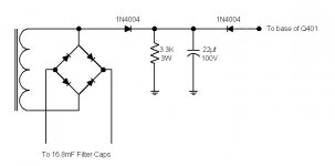
This ought to work...just add the two diodes and the power resistor and the cap. Should pull the base down ASAP and turn the transistor off when powered down. Might have to play with the cap value...22µf might be too big. 10µf maybe...
This ought to work...just add the two diodes and the power resistor and the cap. Should pull the base down ASAP and turn the transistor off when powered down. Might have to play with the cap value...22µf might be too big. 10µf maybe...
Attachments
EchoWars said:I momentarily posted another circuit, till I realized that the current limiting resistor is in the emitter of the Q401. Grrr....
This ought to work...just add the two diodes and the power resistor and the cap. Should pull the base down ASAP and turn the transistor off when powered down. Might have to play with the cap value...22µf might be too big. 10µf maybe...
I will get the parts and try this. Thanks.
Glen
Worth a shot...
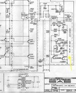
Note that the point of connection of the first 1N4004 is not at the filter caps, but directly from the output of the transformer. This is critical, so that as soon as the switch is turned off, the voltage is lost (as opposed to the voltage on the big 16,800µf 75V caps, which takes forever to bleed off).
The amp also has a separate 6.3V winding for the lamps, which would have been great to use, except with the limiting resistor in the emitter of the relay driver transistor the base will be at too high a voltage for that. So you're stuck with getting the voltage from the high-voltage / high-current winding.
EchoWars said:Worth a shot...
Note that the point of connection of the first 1N4004 is not at the filter caps, but directly from the output of the transformer. This is critical, so that as soon as the switch is turned off, the voltage is lost (as opposed to the voltage on the big 16,800µf 75V caps, which takes forever to bleed off).
The amp also has a separate 6.3V winding for the lamps, which would have been great to use, except with the limiting resistor in the emitter of the relay driver transistor the base will be at too high a voltage for that. So you're stuck with getting the voltage from the high-voltage / high-current winding.
Got it. Thanks again.
djk said:The relay driver circuit has room for improvement.
If you power it directly off the transformer secondary with a half wave rectifier and a 220µF 100V cap, and add a discharge diode for C401 in parallel with R402, the relay will drop out right now on power down. R403 and R407 should be changed to about 120K and 68K. The reason being if one channel dumps to the positive rail, and the other dumps to the negative rail, the relay will not trip with equal value resistors in the integrator.
burnedfingers said:
I have done a number of 2400's in the past and recommend replacement of transistors as well as the caps on the relay board.
Mr. James Bongiorno had his head someplace else when he designed the amplifier. The relay circuit is among its many flaws.
burnedfingers said:
This is worth the modification. I have had a number of 2400's that have come to me with both channels blown sky high. Its not hard to do and it will help safe guard your speakers.
I completed the modification to the relay board and replaced the 4 transistors and single 1N4004 diode with new ones. The pop is gone. Thanks guys.
djk said:Good job!
I was intending the entire relay circuit to be powered by the half-wave rectifier, but EchoWars variation works just as well. It may be easier to retrofit because it does not require any existing wiring to be changed.
Please consider changing R403 and R407 too.
I did implement all of the changes you suggested. I changed the values of R403 and R407 from 100K each to 120K and 68K. Also powered the relay driver circuit with a half-wave rectifier and 220uf cap directly off the transformer secondary (before the main rectifier bridge).
- Status
- This old topic is closed. If you want to reopen this topic, contact a moderator using the "Report Post" button.
- Home
- Amplifiers
- Solid State
- SAE 2400 turn on/turn off pop