Michael,
Check page 7 of the PDF file for the installation of the PA-3C. It shows how to assemble and install the 2.2 film cap and 6800 resistor (bleeder) in parallel to each PS cap. His instruction manual is a little dense, it has a lot of info in it, but it has stood the test of time and most confusing items are very well described.
Don't ground the 3rd wire in a new electrical cord to the chassis. Professional amps do this but they also include a switch to enable lifting this ground. Ground loops can often occur with the grounding of a chassis or two in a system. Most home music systems do not need grounding to the home's supposed earth ground. In fact, I would not use a 3 wire cord. A 16 ga two wire cord is just fine.
Attached is the schematic I use for my time delay relay. I installed it in a separate "turn on" box (actually an old AT computer PS case). I switch this box on and it then turns on the MC amp and the Hafler P-230 currently used to run the subwoofer. The picture shows left and right primary hookups. Actually, I have a duplex outlet on my turn-on box and the amps just plug into this duplex outlet and leave their power switches turned on. You can search the archives here for at least a dozen different soft-start circuits.
Attachments
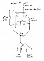
Thanks for attaching the schematic. The time delay relay is something I can just about understand, even with my rudimentary knowledge. I take it that the leads marked NO and NC are pins on the relay (though I don't know what NO and NC mean). And that in this case you have indicated a 100 ohm 50 watt power resistor (earlier you said you used 50 ohm). Other thing is, I don't know what MOV is across the power outlets. I don't know this symbol.
The resistor between the NC pins on the relay shows no value. What do you use for 4-5 seconds?
I missed the item about the PS cap bypass because I thought it was part of the above item, which is for the DH-500 but not the 200.
The resistor between the NC pins on the relay shows no value. What do you use for 4-5 seconds?
I missed the item about the PS cap bypass because I thought it was part of the above item, which is for the DH-500 but not the 200.
Hi Michael,
To quote, copy the text by hilighting it, right click and select copy. When you are posting, click on the "quote" button, above right, and paste the text into the field that pops up.
Those buttons work pretty much as you might think they do. Read directions as they come up.
-Chris
To quote, copy the text by hilighting it, right click and select copy. When you are posting, click on the "quote" button, above right, and paste the text into the field that pops up.
Those buttons work pretty much as you might think they do. Read directions as they come up.
-Chris
Michael,
There are many different types of relays made by a myriad of manufacturers. I selected to use the Potter Brumfield relay with a 120VAC field coil. If you don't use one with a 120VAC field coil you will have to create a power supply for, say, a 24 VAC or 24DC field coil. Also, I ganged together the two sets of 10 amp contacts to create a relay that can switch a 20 amp load.
Most relays function as a type of DPDT switch. The power resistor I showed or described was sized to handle the load I was using. Actually, for just one amp a 25W resistor is OK and a 10 ohm value will give sufficient slowness in voltage ramp up as the PS caps charge in the ~5 seconds when the relay jumpers across the power resistor to remove it from the circuit .
Time for you to do some research, check the archives here, look at what is available on eBay, even use GOOGLE. As you do this you will better understand how to use a relay and what NC (normally closed) and NO (normally open) mean and are used. The relay I showed uses a small resistor soldered between two pins to set delay time. Other models have a dial on the top of the relay to set the time delay and its specific value is particular to this relay only. Here is a listing of time delay relays currently available on eBay:
http://business.listings.ebay.com/R...1QQlopgZ1QQsacatZ78208QQsocmdZListingItemList
The Magnesium Oxide Varistor (MOV) is used here to shunt transients. Do some sleuthing to understand where and why MOVs with different current/voltage ratings are used.
The pin out of many relays is very similar so some study of one model can help understand how to use other models. Also, note where a small film cap should be mounted to reduce arcing at contacts.
Cheers . . . .
Chris, sorry I missed the quote button. I now think I actually saw it first time I posted, then forgot about it as I got absorbed in the subject at hand.
Dick, thanks once again for being so patient with me and answering my questions. The ebay link was a useful orientation. I obviously have a lot of work to do, in numerous areas.
I seem to recall that years ago a simple external device to limit inrush AC line current could sometimes be found in a hardware store. It was used for TV's, I think. I just checked and neither hardware stores nor Radio Shack carries such a device now.
Hi Michael,
What you want is a resistive element that gets shorted out after the main filter caps are mostly charged.
-Chris
I remember them. The thermistor gets hot and is therefore not going to pass UL. Also, it would mess up switching power supplies and Carver type amps.I seem to recall that years ago a simple external device to limit inrush AC line current could sometimes be found in a hardware store.
What you want is a resistive element that gets shorted out after the main filter caps are mostly charged.
-Chris
MichaelP,
Where did you get your CD 22K caps and what was their cost?
Thanks.
Dick
On the big PS caps, I already invested in a pair of new Cornell-Dublier @ 22K uF each, and found they give a nice solid bass with even my stock DH-200, or the modded one, on a single chassis. I don't know how far above the original 10K X 2 total it is safe to go without upgrading the bridge rectifier, but I had an inquiry to Mr Hillig a few months back about that, and he seemed to feel up to 55K or so is no problem, as the stock rectifier can handle it.
Where did you get your CD 22K caps and what was their cost?
Thanks.
Dick
- Status
- This old topic is closed. If you want to reopen this topic, contact a moderator using the "Report Post" button.
- Home
- Amplifiers
- Solid State
- POOGED Hafler transistor blowup