I built an amp with CFP output stage using IRF540N and IRF9540N devices with TIP29C and TIP30C drivers. The upper CFP bursts into oscillation after a short random time after power-up 9/10 times.
I thought I had cracked the design of this amp, just looking if anybody has successfully made a MOSFET CFP/Sziklai, I know Millwood (long time gone) was having problems as well.
I thought I had cracked the design of this amp, just looking if anybody has successfully made a MOSFET CFP/Sziklai, I know Millwood (long time gone) was having problems as well.
Hi Richieboy,
I have designed complemantary mosfet amp with sizklai pair, but it requires some modification though....
1. 220 ohm resistors at the base of driver transistors,
2. R_collector=220ohms and R_emitter=47ohms
3. Rsource=0.47ohms 3Watts
4. 22pF at C-B of drivers
5. UF4004 diodes at C-B of Drivers...
6. Mosfets=IRF540/9540N
7. Drivers MJE340/350
8. Rgate=100ohms+IN4148
9. Gate to Source 7.5V 1W Zeners
Hope this Helps...
K a n w a r")
I have designed complemantary mosfet amp with sizklai pair, but it requires some modification though....
1. 220 ohm resistors at the base of driver transistors,
2. R_collector=220ohms and R_emitter=47ohms
3. Rsource=0.47ohms 3Watts
4. 22pF at C-B of drivers
5. UF4004 diodes at C-B of Drivers...
6. Mosfets=IRF540/9540N
7. Drivers MJE340/350
8. Rgate=100ohms+IN4148
9. Gate to Source 7.5V 1W Zeners
Hope this Helps...
K a n w a r
Thanks Kanwar, I had already implemented a most of what you suggest even with very similar values. A few things to try though, like driver base resistors and driver C-B caps and diodes.
How do the driver C-B diodes help?
I see you have an antiparallel diode on the gate resistor to help with cross-conduction - a good mod I will add if it gets past the not oscillating stage.
How do the driver C-B diodes help?
I see you have an antiparallel diode on the gate resistor to help with cross-conduction - a good mod I will add if it gets past the not oscillating stage.
richie00boy said:Thanks Kanwar, I had already implemented a most of what you suggest even with very similar values. A few things to try though, like driver base resistors and driver C-B caps and diodes.
How do the driver C-B diodes help?
I see you have an antiparallel diode on the gate resistor to help with cross-conduction - a good mod I will add if it gets past the not oscillating stage.
Hi Richieboy,
The C-B Diodes helps very much by facilitating fast recovery from clipping behaviour when the VAS drives the Driver stage much harder....
I haven't experience any thermal biasing problems nor any of the oscillations.....so far!
regards
K a n w a r
Have never seen it done reliably with DMOS/hexfets/vertical based mosfets to be honest - or amp designers advocating it.
Seen it done with lateral power mosfets but I get the feeling some DMOS fets are faster in common source mode than lateral's in source follower mode.
An IRF240 has a GBP above 100mhz and transit times of 1ns or under etc.
I would stick with laterals with a high gain video transistor grade driver. Sanyo's 2SC2911(T) and it's comp. springs to mind. Very linear device.
AndrewT said:Hi,
is SKA by Ampguru a Sziklai connected FET?
Hi AndrewT,
The SKA is not a CFP or a SIZIKLAI type....Its simply behaves like a Common Source amplifier at its output...
K a n w a r
Working MOS CFP IRF530/9530
Just came across this thread, think I may contribute a bit.
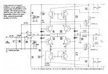
Attached is schematics of working MOS IRF530/9530 output stage, it may look complex but could not figure out a simpler approach to biasing control *and* gate capacitance issues at crossover. This design ensures both devices are allways conducting.
I had to remove some details since part of this amplifier is under patent registration process. Measured performance is comfortably below 0.001% THD.
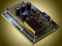
Posted below is a photo of an assembled amplifier module.
Rodolfo
Just came across this thread, think I may contribute a bit.
Attached is schematics of working MOS IRF530/9530 output stage, it may look complex but could not figure out a simpler approach to biasing control *and* gate capacitance issues at crossover. This design ensures both devices are allways conducting.
I had to remove some details since part of this amplifier is under patent registration process. Measured performance is comfortably below 0.001% THD.
Posted below is a photo of an assembled amplifier module.
Rodolfo
Module
Here is one assembled module.
Currently there are 8 amplifiers working inside 4 biamped boxes, though the first 4 were earlier iterations. In all they have probably now over 400 hs. with no problems so far. Sound great for me but this is a biased opinion, others agree too.
Rodolfo
Here is one assembled module.
Currently there are 8 amplifiers working inside 4 biamped boxes, though the first 4 were earlier iterations. In all they have probably now over 400 hs. with no problems so far. Sound great for me but this is a biased opinion, others agree too.
Rodolfo
Attachments
Lumanaw:
Measured stand by current is about 80 mA. Simulations do not work very well I suspect beacuse of poor device modeling. Analytical solutions I found far too messy even with simplifying assumptions so I pushed them to later stages.
Anyway, it is not difficult to gather conceptual criteria for design. basically bias current is established for example for the upper half, by the ratio of T7 emitter resistor (R23) to T2 source resistor (R31) and by T7 emitter current. The circuit tries to equal voltage drop across both.
T7 emitter current in turn is set by R25 (T6 is normaly cut off, works for overload protection) and by T3 driver standby current.
Input is at the junction of R12 - R13 as you found.
Rodolfo
powerbecker said:...no, it´s more like Hegglun (EW1995)
Regards
Heinz!
Interesting Heinz, I was not aware of this design. I notice there is no resistor in T3 (T7) emitter, so stand by current is not very well defined except perhaps - must study further - by T2 (T8).
There is no overcurrent protection provision either, but it is acceptable for a concept prototype.
Rodolfo
There is another even earlier example of your bias scheme in Wireless World, I don't have a scanner hooked up though.
I built an amp like this (without your current limiting) in 1997. You have omitted a couple of caps for clarity I assume.
Rockford Fosgate sold CFP HexFet amps over 20 years ago. Their biggest at that time was 500W/ch. They used an ordinary bias circuit and a 5532 for the front end. Their 100W/ch unit was a huge seller.
- Status
- This old topic is closed. If you want to reopen this topic, contact a moderator using the "Report Post" button.
- Home
- Amplifiers
- Solid State
- Ever made a MOSFET CFP/Sziklai that works?