Hi all,I've been given a Realistic chassis which has been stripped.It used to be a reciever,but all that has been gutted and all thats left is the amp board and psu.It was used as a bridged amp for a sub.The bridge was a basic op-amp affair which has been removed.The amp worked fine for a while then justwent wrong.I put an old loudspeaker on it and the cone sucked in."Ooops",DC on the output.I replaced the speaker for me meter and on both channels it reads 40vdc.Nothing cooks,the relay doesn't cut out and I can't for the life of me know whats wrong.I did an ohms check to see if any of the output trannies are short,but they're ok.I have two IC's with heatsink tabs on them and assume they either are drivers or biasing circuits and I'm not sure how to check them.
Does anyone have a clue?
STA-2270 Digital Synthesized AM FM Reciever.
Cheers.Mikee55 I've got room in me bin for it
Does anyone have a clue?
STA-2270 Digital Synthesized AM FM Reciever.
Cheers.Mikee55
I've got room in me bin for itmikee55 said:I've got room in me bin for it
Hmm..after so much abuse, I'd rather consider it as a museum piece.
/Hugo
fault was there with bridge connected
Hi thankyou for replying.The fault occured with the bridge circuit attached.Thats why I now have the amp.I removed the bridge circuit to see if this made a difference.Thing is my JVC AX-2 went to heaven,and my Technics SU-V2has only one channel and until I build my gain clone Im stuck using the guts from a pair of PC speakers as an amp.I have 7watts per channel to play with.I understand this Radioshag has 75watts.
I wouldn't mind a burnt unit,but this thing looks innocent,nothing visual,I would have thought 40 volts output would give a burnt component or heat,smoke but not a thing.Didn't even blow its fuse.
Doh[/B]
Ah well,worth the try I suppose
cheers
Hello again
Hi,better today.I've taken some readings and I get + 40vdc on both channels,and I've measured the psu at the smoothies and it seems to be fine +/- appx 42vdc.I'm using an analogue meter at the mo,my DMM needs a new battery.
The voltage out of the speaker terminals is +40vdc as in the red terminal is + , there is no negative as the black terminal is ground at 0v.Does this make any sense?
So,Relay operates when its switched on,power supply is ok,output trannies ok and pure DC on the LS terminals,relay should shut the amp down shouldn't it?By the way the longest period I've left it on is less than a minute and I just connected the meter leads to the LS terminals without a load added!
Thanks Mike
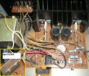
uPC1225H is indeed the frontend for an amp, encompassing the LTP, VAS and driver stages. To be honest that's going to make it pretty much impossible to repair without swapping out the chip, and these things will be well obsolete.
The best you can do here is check that the output stage hasn't failed open, as already suggested. If the output transistors are OK, I would say gut the chassis and use the transformer, psu caps and possibly the output transistors (if they are OK and decent) and build the P3A amplifier.
uPC1237H is a fairly well known amplifier protection circuit IC. It was quite commonly used, but it wouldn't cause the fault you're describing.
input referenced to ground
Hi,not sure if input is referenced to ground.I think I should abort and strip it and look at the P3A amp to see if I could build that.
A big thankyou to everyone who replied.This amp's issue is going way over my head.As is my PC who doesn't want to turn my kids DVDs into Divx files to be stored on my network so they can stream it on their PC's.Anyway,thankyou kindly.Ill be back soon.
Bye for now. Mike Love and Peace to you
Hi,not sure if input is referenced to ground.I think I should abort and strip it and look at the P3A amp to see if I could build that.
A big thankyou to everyone who replied.This amp's issue is going way over my head.As is my PC who doesn't want to turn my kids DVDs into Divx files to be stored on my network so they can stream it on their PC's.Anyway,thankyou kindly.Ill be back soon.
Bye for now. Mike
Love and Peace to you- Status
- This old topic is closed. If you want to reopen this topic, contact a moderator using the "Report Post" button.
- Home
- Amplifiers
- Solid State
- Amp with 40vdc on lts output