hi
I'm new here . It's my first post .
.
I want to build amp for my bass unit (bi amp with push-pull ultralinear EL34 for treble/mid). It will have 100-150W. I post schematic (sorry for quality). Any comments, new ideas? (don't laugh to loud ).
It look like amp form Elektor (autor Giesberts). I made only few changes (especially in the input stage).
"Pre" section will have regulated voltage.
Bias maybe about 200mA
I think about 4 things:
-2 amps/channel (XLR inputs, balanced) would be nice ?
-2, not 4 transistors/channel (especially when balanced)
-different type of output stage (next post)
-different type of driver stage (cascode with constant power, like input stage)
Lenny
I'm new here . It's my first post
. I want to build amp for my bass unit (bi amp with push-pull ultralinear EL34 for treble/mid). It will have 100-150W. I post schematic (sorry for quality). Any comments, new ideas? (don't laugh to loud
). It look like amp form Elektor (autor Giesberts). I made only few changes (especially in the input stage).
"Pre" section will have regulated voltage.
Bias maybe about 200mA
I think about 4 things:
-2 amps/channel (XLR inputs, balanced) would be nice ?
-2, not 4 transistors/channel (especially when balanced)
-different type of output stage (next post)
-different type of driver stage (cascode with constant power, like input stage)
Lenny
Attachments
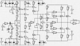
I just took a quick look, so I may be in error, but a couple of things I have noted:
1. Your use of AC coupling on the input but not the output. Why not use a fully DC coupled design?
2. I see only a pure resistive feedback network. You should use a capacitor to roll off the high frequency response.
3. You might also wish to use a capacitor in the main feedback loop to reduce the DC gain to 1 (highly recommended in DC coupled amplifiers).
4. Your driving the FETs from a common emitter configuration seems like a bad way to go. I would recommend driving them from emitter followers - with 150 collector resistance like you have, I would think the transient performance would be poor.
Hope this helps.
Jeff R.
In a current feedback amplifier
you do not use the usually frequency filter capacitor
in the global feedback
It is done somewhere else,
but where?
This one uses the emittors of transistors as the feedback
input (the inverted input)
DC input I use when I want DC outputs.
Like when playing AC/DC.
I use caps,
mainly because my speakers have so bad
response for frequencies BELOW 20 Hz
I know I miss that part of the music
But what can you do what such bad speakers?
Re: Nice schematics!
Looks like it was done with Protel for Windows that came out in the early 90's. I have one that they outgrew at work.halojoy said:I wish I could get such quality
in my schematic pictures.
Thank you for comments.
Yes, that's Protel Protel SE form their www page (trial version ).
I forgot to mention that DC offset wil be done with DC Servo, so maybe this capacitor in input is realy bad idea.
Hi frequency behaviour is depended on C7, C8. I hope this is enough. Correct me if I'm wrong. I'm litle worry about oscilations, because I don't have osciloscope.
Yes, that's Protel
Protel SE form their www page (trial version ).I forgot to mention that DC offset wil be done with DC Servo, so maybe this capacitor in input is realy bad idea.
Hi frequency behaviour is depended on C7, C8. I hope this is enough. Correct me if I'm wrong. I'm litle worry about oscilations, because I don't have osciloscope.
Lenny if you want to study the concept of current feedback, check ON and National.
http://www.national.com/search/search.cgi?keywords=current feedback&full=1#App
Have some trouble to find at ON but I know they have good documents.
http://www.national.com/search/search.cgi?keywords=current feedback&full=1#App
Have some trouble to find at ON but I know they have good documents.
Ohmmm....
Meybe you could change first&second stages to one j-fet stage.
You could take a voltage gain and very good input bufer ( it have really high input imedance ). It is a possibility to connetc NFB with the current mode.
There is a great amount of negative feedback in last two stages, I,m affraid it could oscilate.
You have to design a system to prevent volage peaks, because Hexfets could burn to death. Maybe a capacitor across bias stabiliser, meybe zener diodes or system that slowly raises PSU voltages.
Dobra Lenny pogadamy na Aikido.
I have seen small capacitorhugonot said:--------------------- ..... --------
There is a great amount of negative feedback in last two stages, I,m affraid it could oscilate.
-------- ........ ----------
Dobra Lenny pogadamy na Aikido.
across R27, 33 ohm
in this type of output stage with a voltage gain
Also is good, maybe nessesary,
with a separate Power Supply for the output stage
for Current Feedback Amps.
They are more sensitive for such feedback.
This is already done here.
DC-servo. Why?
Nelson said somewhere that he can tolerate some 0.500 volt.
How much watt is that?
Would it ruin your speaker?
I know that I would give such a speaker away to charity
or better to destruction!
You will get far, far less DC-offset than 0.500 volt,
if you trim your amplifier.
Isn't it better to use some delay and a relay,
until DC-offset settles?
peranders said:Lenny if you want to study the concept of current feedback, check ON and National.
http://www.national.com/search/search.cgi?keywords=current feedback&full=1#App
Have some trouble to find at ON but I know they have good documents.
check out www.ti.com also
Only as a short term proposition (warming up). 100 mV ishalojoy said:Nelson said somewhere that he can tolerate some 0.500 volt.
my acceptable limit for most speakers, and I like a lot less
than that.
BTW, 0.500 V is 1/16 watt into 8 ohms.
My 50w class A has 325mv offset all the time. Is the dc drop across the output choke @ 3.5 amps. Would be nice if it didn't but I don't think it has any real detriment to the sound, especially if you don't know about it. That last bit sounds funny but I think it has quite some truth to it.
Hi Lenny
I once performed simulations on a circuit that was a little similar to yours.
The main difference is that mine is inverting and it's input stage is a little simpler than yours. The simulation results looked promising.
http://www.diyaudio.com/forums/showthread.php?threadid=7058
I particularly like the output stage on your first schematic. The first reason (as you already mentioned) is that it can be driven very close to the rails. The second reason is that lower Vce driver transistors can be used.
I don't think that this is topology is very critical regarding stability.
I haven't found the time to try my circuit out so far but a workmate of mine is very curious about it's performance and will most probably try it out.
Good luck with yours
Charles
we share diy-listen with friends/family
to anyone person surrounding us
i do it a lot - specialy my eldest brother asks me many advices about his soundsystem
- i have designed, my own, hifi headph-amp
custom made to suit his headphones - he bought model after advice given (Sennheiser 600)
watch me know - i am the american dream
some links on amplification design tubes/transistors at
Music&Mp3 Page of Groman the Swede
in't it nice we can give "sound advices"phase_accurate said:Hi Lenny
http://www.diyaudio.com/forums/showthread.php?threadid=7058
I particularly like the output stage on your first schematic.
I haven't found the time to try my circuit out so far but a workmate of mine is very curious about it's performance and will most probably try it out.
Good luck with yours
Charles
to anyone person surrounding us
i do it a lot - specialy my eldest brother asks me many advices about his soundsystem
- i have designed, my own, hifi headph-amp
custom made to suit his headphones - he bought model after advice given (Sennheiser 600)
watch me know - i am the american dream some links on amplification design tubes/transistors at
Music&Mp3 Page of Groman the Swede
- Status
- This old topic is closed. If you want to reopen this topic, contact a moderator using the "Report Post" button.
- Home
- Amplifiers
- Solid State
- my new amp (comments?)