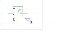
Normally, the macro model for an opamp is a voltage controlled voltage source (see picture), where the gain factor is very high and the output cotrolled voltage source is referenced to ground.
==> If I use an opamp with its own separate floating supplies and do not connect them to actual circuit ground, will the macro model change to an output voltage source that is truly floating (IE not referenced to ground)?
==> If I use an opamp with its own separate floating supplies and do not connect them to actual circuit ground, will the macro model change to an output voltage source that is truly floating (IE not referenced to ground)?
Attachments
Floating supply op amps may be modeled with some of the “multiple pole-zero” models that TI and Analog devices have presented in their app notes
But they don’t use them uniformly or often, many Boyle style macromodels are still being released
So you have to look inside the model to tell – Spice node 0 should not appear inside a op amp model
Once you start digging in you realize how poor many models are and you might just roll you own with 1-2 poles and a output resistance to generically play with bootstrapping
Here I point out some of the problems I had with the author of the AD8610 op amp model:
http://www.diyaudio.com/forums/showthread.php?s=&threadid=13590&perpage=10&highlight=&pagenumber=2
The OPA227 model seems to get gain right – I‘ve not tested whether output current appears plausibly in the ps terminals – yet another layer of modeling accuracy
I have been playing for several years with power supply bootstrapped op amp circuits
One previously known composite op amp with power supply bootstrapping showing loop gain enhancement from the bootstrapping of the internal voltage gain stage is from Mohapatra and Sandman’ 1980 GB patent
The sim shows Mohapatra&Sandman’s topology with the OPA227 model, I call this a feedforward bootstrap topology
The loop gain is substantially boosted by the bootstrap connection when the load impedance Rload is high
Because the OPA227 is in series with the bootstrap amp there is no improvement in its output impedance so you can see the gain boost disappears with heavier loading
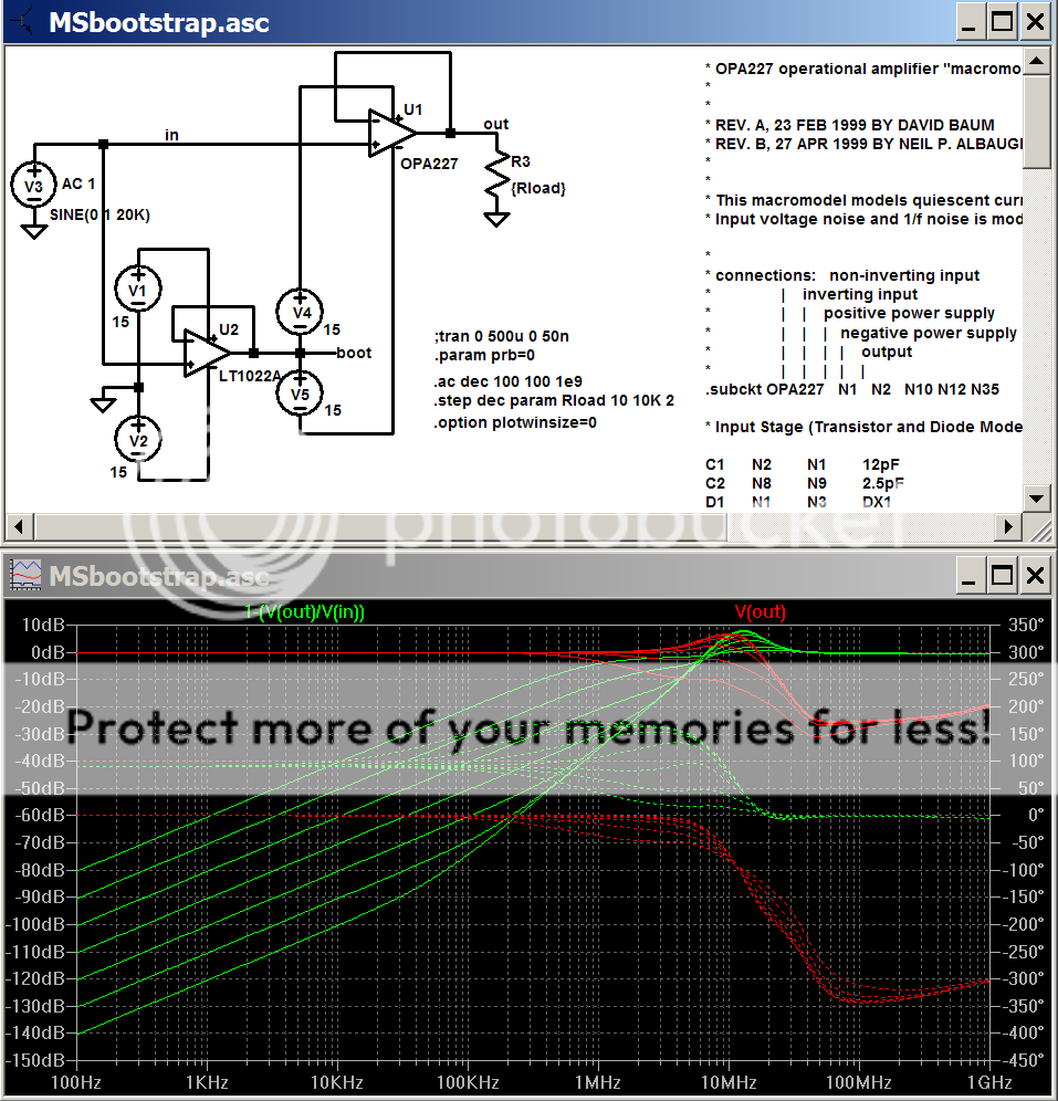
The “loop error” I’ve plotted (in green) is essentially the inverse of the loop gain – at 10 KHz with the high load impedance you can see 100 dB loop gain => 1 GHz “GBW”
But they don’t use them uniformly or often, many Boyle style macromodels are still being released
So you have to look inside the model to tell – Spice node 0 should not appear inside a op amp model
Once you start digging in you realize how poor many models are and you might just roll you own with 1-2 poles and a output resistance to generically play with bootstrapping
Here I point out some of the problems I had with the author of the AD8610 op amp model:
http://www.diyaudio.com/forums/showthread.php?s=&threadid=13590&perpage=10&highlight=&pagenumber=2
The OPA227 model seems to get gain right – I‘ve not tested whether output current appears plausibly in the ps terminals – yet another layer of modeling accuracy
I have been playing for several years with power supply bootstrapped op amp circuits
One previously known composite op amp with power supply bootstrapping showing loop gain enhancement from the bootstrapping of the internal voltage gain stage is from Mohapatra and Sandman’ 1980 GB patent
The sim shows Mohapatra&Sandman’s topology with the OPA227 model, I call this a feedforward bootstrap topology
The loop gain is substantially boosted by the bootstrap connection when the load impedance Rload is high
Because the OPA227 is in series with the bootstrap amp there is no improvement in its output impedance so you can see the gain boost disappears with heavier loading
The “loop error” I’ve plotted (in green) is essentially the inverse of the loop gain – at 10 KHz with the high load impedance you can see 100 dB loop gain => 1 GHz “GBW”
Attachments
jcx:
Thank you for your great reply!
I skimmed through the sources you listed, and I was surprised at how "simple" some of the manufacturer's models were. Many of their "g" and "e" controlled sources were referenced to ground when it seems to me that they should not be.
==> I think vendors should provide their netlists and symbol models with an extra pin on their models called a "reference" pin. This would be the opamp's internal "ground" reference, which may or may not be connected to the application circuit's actual ground. No node 0 should be used in a decent spice model netlist because there is no guarantee that the model will be connected to real ground.
- Status
- This old topic is closed. If you want to reopen this topic, contact a moderator using the "Report Post" button.