I breadboarded this as a proof-of-concept circuit, and it worked. But I'd like to get some additional opinions on it before implementing it in my own DIY amp project...
I'll post the schematic as its own post so it won't scroll text, as in order to make it big enough to read it's too big to fit without scrolling. After that comes the explanation of the basic idea.
oO
I'll post the schematic as its own post so it won't scroll text, as in order to make it big enough to read it's too big to fit without scrolling. After that comes the explanation of the basic idea.
oO
The circuit's supply voltage (Vss) is 12VDC, and given the all-MOSFET construction my test version only pulls a few milliamps.
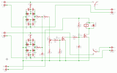
The basic idea of this is to rectify the output of each channel, and use the resulting DC to charge a capacitor (in this case, C9). A rectifier bridge is used for each channel, with all diodes bypassed by capacitors to dampen electrical noise caused by the diode junctions. I have 1N4002s listed, but suspect that a set of fast- or ultrafast-switching small-signal diodes would be better, provided that they can handle the reverse voltages from the amplifier. (1N4148s are only good to about 60VAC safely in this design.)
Ordinarily, when the circuit is first powered up, Q1 starts off biased off by R9, and Q2 starts biased on by R11. Q2 would thus power the relay K1 and switch the channel inputs to the corresponding outputs. C10 initially charges through R11, and this causes a turn-on delay of about half a second or so.
A variable voltage divider across this capacitor (R5-R7) allows setting the maximum charge that will trip the gate of Q1 - the trimmer R7 needs to be set to produce JUST under the switching voltage of Q1 (usually around 3.3VDC for an IRF-series power MOSFET) when the amp is running at its maximum safe operating power into the minimum safe impedance load.
When Q1 is switched on, it grounds the gate of Q2 through R10, causing Q2 to turn off and let the relay K1 switch the outputs out of circuit. C10 provides a turn-on delay of about three seconds after Q1 switches back off, in order to give any momentary fault time to correct itself or let supply-rail fuses blow if a driver device is shorted, etc.
Although the schematic doesn't show this, I had a 1,000uF electrolytic capacitor and a 0.1uF mylar capacitor across Vss in order to dampen any supply transients that may cause false-positive reactions from Q1.
Anyway, it works on my breadboard when an amp is connected to it, and I didn't note any discernible changes in the sound quality.
Any opinions on this design?
oO
I would use a logic triac for Q1 and ditch all the rectifier diodes. I would also use a two-pole low pass filter to avoid false triggering from bass. And use a triac for each channel. With a common low pass filter/trigger device it could fail to protect if one channel puts out a possitive voltage while the other puts out a negative voltage.
C10 needs a discharge path in order to refresh the timing cycle on a brief on/off cycle. A DC voltage that is half-wave rectified and lightly filtered with a diode reversed biased to the gate of Q2 will do. This voltage will collapse first allowing C10 to quickly discharge through the now forward biased diode into the collapsed supply.
C10 needs a discharge path in order to refresh the timing cycle on a brief on/off cycle. A DC voltage that is half-wave rectified and lightly filtered with a diode reversed biased to the gate of Q2 will do. This voltage will collapse first allowing C10 to quickly discharge through the now forward biased diode into the collapsed supply.
djk said:I would use a logic triac for Q1 and ditch all the rectifier diodes. I would also use a two-pole low pass filter to avoid false triggering from bass. And use a triac for each channel. With a common low pass filter/trigger device it could fail to protect if one channel puts out a possitive voltage while the other puts out a negative voltage.
I see where you're going with it and it sounds fine in theory, but I've noticed from other unrelated circuits that triacs are a LOT more noisy electrically than a well-made rectifier bridge. Logic triacs should be a lot better about that than conventional power ones, but I'd then be concerned about the voltages across them exceeding their operating limits. Might be a serious and possibly unresolvable issue for audio systems.
However, the filter is not a bad idea. I might have to see about simulating a few variations and seeing what shakes.
My current design's rectifier-bridge implementation seems to cure the possibility of channels shorting to opposite rails, so that won't be an issue I don't think.
C10 needs a discharge path in order to refresh the timing cycle on a brief on/off cycle. A DC voltage that is half-wave rectified and lightly filtered with a diode reversed biased to the gate of Q2 will do. This voltage will collapse first allowing C10 to quickly discharge through the now forward biased diode into the collapsed supply.
I thought about doing that very thing with a tap off the unfiltered side of a rectified supply to put a quick short on C10, but actually trying that ended up killing the slow-restart from fault that the circuit exhibits from C10 having to recharge through R11 after Q1 switches off. As it is, when Q1 is switched off it shorts C10 to ground through R10 and it drains the charge pretty quickly. Apparently, under real world loads having C10 charge through R11 makes it not switch the outputs back on too fast (and possibly while still in overload) after a fault, and having it discharge through R10 makes it not as prone totripping on a transient unless said transient has enough duration.
When I ran the circuit right at its trigger threshold with a reverse-biased pulsating DC applied to C10's positive terminal, Q2 would switch on and off like crazy, a condition that is not exactly a good one to have happen in practical application. If anything, it might be necessary to decrease the size of C10 to decrease its charge time and shorten the recover-to-on time from faults. I also thought about decreasing the value of R10 to make C10 discharge faster when Q1 switches on because of a fault.
Some early tests and simulations seem to suggest that my initial protection circuit would do well as a fault detector for too much DC (~4 volts looks to be the trip point) on the outputs and large-enough/long-enough transients, as well as dealing with short-to-rail conditions if a final stage device toasts itself. Still need to run more tests and tweak the circuit some though, and then do the all-important listening tests.

oO
(Edited to correct my lousy typing.)
another thread about triac protection:
http://www.diyaudio.com/forums/showthread.php?threadid=5083&highlight=triac+crowbar
Best regards,
HB.
http://www.diyaudio.com/forums/showthread.php?threadid=5083&highlight=triac+crowbar
Best regards,
HB.
Hmmm, not sure I want to use triac-crowbar protection for the amp's supply rails as some knucklehead ALWAYS thinks he has to tinfoil a fuse when it pops. However, I think I could add another stage to my original circuit design to add the ability to kill the AC feed to the transformer by crowbarring the main breaker up from it.
oO
oO
- Status
- This old topic is closed. If you want to reopen this topic, contact a moderator using the "Report Post" button.
- Home
- Amplifiers
- Solid State
- A schematic idea for speaker protection...