Hi all,
I found something odd with my Quad 405. When idle with no input and no speakers connected it runs hot in a couple of minutes on my testbench. The output transistors are connected to a 4x50x130mm piece of Al.
In Bernd Ludwig's mods F1 Appendix it's explained how the circuit works so I checked the voltages on my Quad and I don't understand why the colector of Tr7 is with more than 1.2V above the specified.
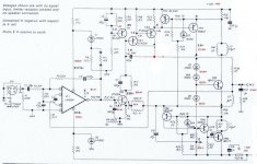
In the attached image I wrote the voltages from my Quad on the original design with two mods specified with red dots (I know that it's ugly...). Also I implemented Bernd Ludwig's other modifications and the input mod from dc-daylight.co.uk
Do you have any ideeas where should I start do debug?
Thank you,
Zsolt
I found something odd with my Quad 405. When idle with no input and no speakers connected it runs hot in a couple of minutes on my testbench. The output transistors are connected to a 4x50x130mm piece of Al.
In Bernd Ludwig's mods F1 Appendix it's explained how the circuit works so I checked the voltages on my Quad and I don't understand why the colector of Tr7 is with more than 1.2V above the specified.
In the attached image I wrote the voltages from my Quad on the original design with two mods specified with red dots (I know that it's ugly...). Also I implemented Bernd Ludwig's other modifications and the input mod from dc-daylight.co.uk
Do you have any ideeas where should I start do debug?
Thank you,
Zsolt
Attachments
Hi,
They shouldnt run hot at all, i built a 405 a while ago and they o/p transistors were stone cold until a signal and load were connected. The only time they ran hot was when i accidently put them into class A operation (lol dont do this!).
If the driver transistors run hot however this is fine as they are running class A by design, Tr7 should be noticably hot/ warm at idle.
The collector of TR7 is more positive because you have added another diode to the bias set up, although i dont know why it has increased two diode drops?
I am no where near as clued up on electronics as lots of others here, so i hopw what i said is helpful to you.
I reckon that you circuit is likely to be fine, as long as the output transistors remain cool i think your just feeling the class A driver heat up.
Regards
Craig
Craig,
Yes, the voltage drop on the diodes it's strange for me too. I changed them to 1N4007 and now the woltage drop is around 0.7V on them.
Reading Bernd's explanation about how the output stage is working I
made some more measurements having the amplifier in idle (no input, no speakers).
The "idle current" (the current that runs down through R30/31) is ~50mA (wich is good having 55V instead of 50V); the current through R38 when idle is ~34mA and the current at Tr8 collector is ~22mA (~0.5 enough to open Tr10).
Maybe I missunderstood the explanation of how the dumpers are working but I found strange that the base voltage of Tr10 in idle mode is enough to open (~0.5V) it. So both Tr8 and Tr10 are working in idle.
Also, the base-emiter voltage of Tr9 is 0.27 when idle, and even if I connect the speakers and put some music (having ~10W) it increases only to ~0.35V, which is not enough to open it. As I understand the whole positive output-swing has to be dumped by Tr7.
Any ideeas are welcomed!
Zsolt
In the previous message I missed the question ")
Is it normal with the Quad 405 to have the following values:
In idle (no input, no speakers connected) to have:
- a current of ~34mA running through R38 ?
- a collector current of ~-22mA for Tr8 (~0.5V (with respect to V-) enough to open Tr10) ?
- a base voltage of ~0.27V (with respect to the emiter) for Tr9 ?
Having a source signal (music) of ~100mV at the input + speakers connected to the output to have:
- a current of ~38mA running through R38 (I have added D13 as suggested) ?
- a base voltage of ~0.35V (with respect to the emiter) for Tr9, so not enough to open it ?
I'm just a hobby electronist so maybe I missundertstood something in the design or functioning of the Quad 405.
Thank you,
Zsolt
Keith,
I moved C8 to the collector of Tr2 and I took out R23 and shorted C11.
I also took out the components that are part of the limiter circuit.
I tried to move C8 to the emiter of Tr2 but it oscillates on a hearable couple of KHz (at least I think so) and the offset voltage (the output voltage with no input and no speakers) raised from ~0.5mV to 40-50mV. I moved C8 back to the collector of Tr2 then. Unfortunately I don't have an oscilloscope to see the real output signal.
I haven't checked for high frequency oscillation but I'm starting to think that could be the real problem. The PCB is handmade and has lot's of straps in the output part and three prity big home made inductors which are very close to each other. The output transistors are 2SC5200 which are fast and the OPA627 is sensitive too. I tried a couple of modifications on the PCB so it looks like a trench.
I simulated the circuit with Workbench and with D13 inserted the voltage at the collector of Tr7 (when idle) is ~1.29V, what really should be. It remained at ~1.29V even if I increased the PSU voltage from +-50 to +-55V. I have a PSU with +-55 after rectification. The collector voltage raised only if I put a signal to the simulated input. The simulated Quad started clipping for an output of ~34V and input 1.27V. I think these values are ok.
I think I will drop this homebrew design and buy a ready made hungarian Quad 405 clone, like the one on the link, and do the modifications in half a day. The clone cost is ~25euros , maybe not audiophile capacitors but that could be changed with time.
Regards,
Zsolt
I moved C8 to the collector of Tr2 and I took out R23 and shorted C11.
I also took out the components that are part of the limiter circuit.
I tried to move C8 to the emiter of Tr2 but it oscillates on a hearable couple of KHz (at least I think so) and the offset voltage (the output voltage with no input and no speakers) raised from ~0.5mV to 40-50mV. I moved C8 back to the collector of Tr2 then. Unfortunately I don't have an oscilloscope to see the real output signal.
I haven't checked for high frequency oscillation but I'm starting to think that could be the real problem. The PCB is handmade and has lot's of straps in the output part and three prity big home made inductors which are very close to each other. The output transistors are 2SC5200 which are fast and the OPA627 is sensitive too. I tried a couple of modifications on the PCB so it looks like a trench.
I simulated the circuit with Workbench and with D13 inserted the voltage at the collector of Tr7 (when idle) is ~1.29V, what really should be. It remained at ~1.29V even if I increased the PSU voltage from +-50 to +-55V. I have a PSU with +-55 after rectification. The collector voltage raised only if I put a signal to the simulated input. The simulated Quad started clipping for an output of ~34V and input 1.27V. I think these values are ok.
I think I will drop this homebrew design and buy a ready made hungarian Quad 405 clone, like the one on the link, and do the modifications in half a day. The clone cost is ~25euros
, maybe not audiophile capacitors but that could be changed with time.Regards,
Zsolt
I meant it could be the OPA627 oscillating, the spec sheet says that you must put 0,1uF caps on the +/- to ground. The "power supply" to the opamp is very crude - only a zener. You can also try putting a 22uF tant over the zeners + the 0,1uF caps...use the TL071 to test if the osc. stops...
All
Forgive me if I don't follow this in a timely fashion but I really must "fly" for a while.
Zsolt
If you placed C8 at the emitter of Tr2 and followed all my other changes - as it appears you have- then all should work OK.
I think that money spent on a good oscilloscope would be worth while - you will get a new perspective on what's going on with your mods.
If you look at all QUAD designs from 405 onward it is clear that HF/RF oscillation has been a problem - a problem often cured by fitting inductors - in the case of the 405 THERE IS NO BENEFIT in making good quality inductors apart from L2 an even here some loss may actually help stability i.e. R44 on later models.
Also if you have to fit capacitors around op-amps or across transistors then perhaps consider fitting different parts that work without them - LESS REALLY IS MORE.
Best regards
Keith
Hallo, All,
I am now putting a full step-by-step instruction guide with pictures for upgrading and revising a 405-2 on http://quadrevisionspot.blogspot.com/.
Feel free to take a look and post your comments
Stefaan
I am now putting a full step-by-step instruction guide with pictures for upgrading and revising a 405-2 on http://quadrevisionspot.blogspot.com/.
Feel free to take a look and post your comments
Stefaan
Stefaan, I think your Quad 405 revision is very useful, so keep on writing. Of course take your time to have enough cool drinks, it's summer .
I would like to ask you something: could you please send me a picture with the back side of the Quad 405-2 pcb board posted on your site. I plan to make a clone of it incorporating the modifications suggested by Keith and tvicol.
Regards,
Zsolt
.I would like to ask you something: could you please send me a picture with the back side of the Quad 405-2 pcb board posted on your site. I plan to make a clone of it incorporating the modifications suggested by Keith and tvicol.
Regards,
Zsolt
Regarding the problematic Quad 405.
I simulated the Quad 405 with Workbench and the voltage at Tr7 collector rises to 1.65V only when there is an input signal of ~40mV. When idle it has 1.29V (because of D13 inserted).
I might have some oscillation problems so I will try to do one more thing with it, to change back the BB627 with the old TL071. The pcb's were made after some hungarian Quad clones and I'm not sure they are rightly done. I think it will be better to clone the original Quad and do the modifications on it.
Regards,
Zsolt
Hi V,
is the input open circuit? or connected to a source without a signal present?
I assume the 301 has been replaced with the 627, I think this may be the problem.
Try that replacement back to 072 you mentioned earlier and ensure the input is loaded with a low source resistance or even a shorting plug.
is the input open circuit? or connected to a source without a signal present?
I assume the 301 has been replaced with the 627, I think this may be the problem.
Try that replacement back to 072 you mentioned earlier and ensure the input is loaded with a low source resistance or even a shorting plug.
Hi Andrew,
If I leave the input on open circuit I have a small hum/noise in the speakers. When I connect the input to a source (CD player) without a signal present this hum/noise goes away, only a faint hiss, hearable only if I stick my ears on the speakers.
Thanks for the tip, I will try to put the TL071 back tomorow. If thats the problem with Tr7's collector voltage I will regret to take out the 627's... will see.
Regards,
Zsolt
Hi, Zsolt,
To my experience the BB 604 is less sensitive to oscillation than the BB 627 (or 637).
In both cases you should foresee 100 nF caps in the power-supply lines of the chip.
I'll send you a picture of the backside of the PCB tomorrow and maybe I'll put an article about oscillation on the blog. But first I have to finish the upgrade-instructions
Stefaan
I tried to put back the TL071 but the problem remained. The voltage at Tr7 collector is still 1.65V.
The noise increased a bit but the output idle voltage is ok with ~1mV.
In Workbench simulation there is no problem if I increase the voltage to +-56V (as I have). The current through R30/R31 increases to 50mA's as I measured in the real circuit, but the voltage at Tr7 remained at 1.29V (more with ~0.6V due to D13).
If you think that +-56V is too much for the Quad 405, what do I have to change in order to work with that voltage. Maybe increase R30/31 from 560 to 610, or what else?
I would like to keep my new 400VA toroidal wich has 2 x 41-0-41 in secondaries.
Thank you,
Zsolt
- Status
- This old topic is closed. If you want to reopen this topic, contact a moderator using the "Report Post" button.
- Home
- Amplifiers
- Solid State
- Quad 405 output voltages problem