Hi there
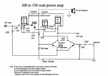
I found a 100-150w circuit on the web and decided to build it.
It comprises two darlingtons tip 142 and 147. The other transistors are tip 41, and two Bc 558.
After two attempts the BC 558 that is linked to the + voltage bursts.
I am also measuring 45 volts across the speaker leads. Is this normal?
Has anyone built this circuit? Did it work?
It a pretty simple circuit and I would really be pleased if it works.
If anyone has a simular simple circuit with matching power that works well, can u please let me have a look.
By the way I could locate the Tip 147 so I used the replacement NTE 271.
Attachments
Still in midst of reading other thread provided (thanks, didn't come up in searches for me before)
I built it... had some hiss and vulnerable. Had decent sound and punch . Gain seemed too high. I was running of 39-40 volt rails. Also has some problems where it didn't seem to settle in and sounded very distorted once in this funky state (bias?). It was like I needed to turn it on with no input, let it sit for a bit, then ran good. Then tried changing my input caps as I had small ones in, 1uf rather than 4.7uf electrolytic in schematic, to some 5.0uf crossover caps to test and smoked the amp. Haven't gotten around to trying again as I have more 142 and 147s on hand as I know it has some inherant problems.
Will study the other thread as will be a good learning exercise
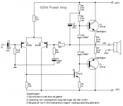
A few years ago I reconstructed the following schematic from the drawing shown in the start of this topic.
Remarks:
1) Note that the output transistors are darlington's
2) This is real Class B design (bias current in output stage is 0), so you can expect quite some crossover distortion, especially at low volume levels and high audio frequencies.
3) Do not expect hifi quality from this design. I do not recommend to build this schematic other than for educational purposes.
4) Like mentioned by richie00boy below, it is not unlikely that this amplifier will act as oscillator.
5) It is very well possible to improve performance by means of a few simple design changes.
Attachments
I also built this circuit as my first amp and indeed it is a 100 watt oscilator. I'm by no means an expert or even remotely qualified to give analysis on circuits but I did design and build a circuit based on that one that I have been using for about a month. It performs well and has decent sound quality but is great for learning your way around. Hope it works for you and remember, no matter how tempting it may seem NEVER stick your tongue accross the big black nichicons 
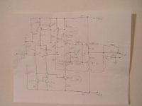
In looking at the schematic in post #6, I sketched out a few ideas to improve that circuit but still keep the basic idea, just a few peripherals such as the mirror to balance the current in the diff-amp stage and a current source to set and limit it. Might keep the BC556's from exploding. A CCS to load the VAS with BD139/140's. Vbe multiplier is a must for these darlingtons if they are to be biased in class AB to compensate the temperature coefficient and maintain thermally stable bias. 10-50pf cap for miller feedback may help with stability. Finally a Zobel network may also help quell oscillations.
Wouldn't expect get more than around 50-60WRMS from one pair of these.
Any other quick improvement ideas from the actual 'experts' out here? and to point out where I went wrong.
I might be willing to try this circuit if the TIP141's I have in my drawer weren't fakes...and bad ones at that! getting ripped off is quite irksome.
A CCS to load the VAS with BD139/140's. Vbe multiplier is a must for these darlingtons if they are to be biased in class AB to compensate the temperature coefficient and maintain thermally stable bias. 10-50pf cap for miller feedback may help with stability. Finally a Zobel network may also help quell oscillations. Wouldn't expect get more than around 50-60WRMS from one pair of these.
Any other quick improvement ideas from the actual 'experts' out here?
and to point out where I went wrong.I might be willing to try this circuit if the TIP141's I have in my drawer weren't fakes...and bad ones at that!
getting ripped off is quite irksome.Attachments
There is still no pole compensation, so it will at some point turn into a power oscillator, and the DC offset adjust method is very poor as it changes the gain/degeneration of each side of the LTP which is compounded by the current mirror trying to fight it from the other side.
With the increase in gain from the CCS on the LTP tail and more gain from the high dynamic impedance of the current mirror, this design will be even harder to stabilise than the original.
I appreciate what you have tried to do with the design, but I'm afraid it's a classic case of fiddling with fundamental aspects when you aren't quite sure what you are doing.
Hi,
post10 could use a series resistor & cap from VAS collector to inverting base in parallel with the cap already shown. Gives more flexibilty for debugging.
Add a series resistor & cap in parallel to non inverting LTP collector load i.e. from VAS base to -ve rail. Again for debugging.
Remove the decoupling caps, speaker and Thiel network (nice) from the signal (clean) ground.
Add in a power (dirty) ground for these components and lead them direct to the central star ground.
Add a resistor from signal ground to dirty ground.
Add a terminal for RCA input ground next to the signal ground terminal to go to central star ground.
Richie,
I think the cap shown circled is the pole compensation but removed from the VAS base to collector where it degrades sound quality.
AndrewT said:Hi,
post10 could use a series resistor & cap from VAS collector to inverting base in parallel with the cap already shown. Gives more flexibilty for debugging.
Add a series resistor & cap in parallel to non inverting LTP collector load i.e. from VAS base to -ve rail. Again for debugging.
Never had call for those in any amp I've ever seen or built
AndrewT said:Remove the decoupling caps, speaker and Thiel network (nice) from the signal (clean) ground.
Add in a power (dirty) ground for these components and lead them direct to the central star ground.
Add a resistor from signal ground to dirty ground.
Add a terminal for RCA input ground next to the signal ground terminal to go to central star ground.
Yes, very sound advice.
AndrewT said:Richie,
I think the cap shown circled is the pole compensation but removed from the VAS base to collector where it degrades sound quality.
Degrades sound quality? Miller effect compensation is probably the most effective way of stabilising an amplifier. Of course if it is not implemented properly it can effect things, but properly done it works great.
Hi Richie,
fitted to a number of commercial amps I currently have and all sound great. Also used by JLH and seems to be more common on British designs.Never had call for those in any amp I've ever seen
we will just have to disagree.Miller effect compensation
Two different opinions:
#1 Lag compensation swamping Miller capacitance across VAS bc junction.
#2 Phase lead pulling back OLG from VAS collector to inverting input.
One is tempted to choose. This is only human!!
But, as in so much of nature, why not use both?
LC is very effective but if overdone ruins sonics.
PL has the benefit of little sonic impact and improves tolerance to capacitive loading.
Try both.
Set up for marginal stability with LC then augment with PL.
Cheers,
Hugh
Personally I prefer phase lead feedback to VAS base to collector in the case of a single VAS/CCS. With a good diff stage, can be fairly stabilized without too much sonic degradation...depends on components I suppose.
Hey, I'm only human
richie, the DC offset is in fact bunk, doesn't work. I'm not sure where that came from.  ...
... Anyway, there are still obviously issues with the circuit for it to be perfect, but it would be good to actually build it, observe the behavior, then play amp doctor.
 After all, there are better transistors out there than TIP142/147.
IMO cheap transistors are better to use to learn with a circuit like this than 's ones.
Hey, I'm only human
richie, the DC offset is in fact bunk, doesn't work. I'm not sure where that came from
. ... Anyway, there are still obviously issues with the circuit for it to be perfect, but it would be good to actually build it, observe the behavior, then play amp doctor. After all, there are better transistors out there than TIP142/147. IMO cheap transistors are better to use to learn with a circuit like this than
's ones. - Status
- This old topic is closed. If you want to reopen this topic, contact a moderator using the "Report Post" button.
- Home
- Amplifiers
- Solid State
- 100-150watt amp