Hi,
it is quite normal to have a DC blocking cap and RF filter on the input to a power amplifier.
I would recommend you keep to that.
However your values are a bit unconvential.
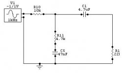
4u7F and 221r gives an RC time constant of 1.04mS and rolls off the bass from 1.5kHz at -6db/oct.
Could that be a misprint and r1=22k? Then the -3db frequency changes from 1.5kHz to 1.5Hz.
If your source has a DC blocking cap at it's output, then you can bypass the input cap to the power amp.
The 10k series into the combined 47nF + 4k7 is beyond my maths/electronics analysis knowledge. But usually you aim for an RC time constant of 0.5uS to 2uS to roll off the ultrasonics and RF.
1k0 and 1nF achieve this plus a range either side depending on your preference and signal bandwidth.
it is quite normal to have a DC blocking cap and RF filter on the input to a power amplifier.
I would recommend you keep to that.
However your values are a bit unconvential.
4u7F and 221r gives an RC time constant of 1.04mS and rolls off the bass from 1.5kHz at -6db/oct.
Could that be a misprint and r1=22k? Then the -3db frequency changes from 1.5kHz to 1.5Hz.
If your source has a DC blocking cap at it's output, then you can bypass the input cap to the power amp.
The 10k series into the combined 47nF + 4k7 is beyond my maths/electronics analysis knowledge. But usually you aim for an RC time constant of 0.5uS to 2uS to roll off the ultrasonics and RF.
1k0 and 1nF achieve this plus a range either side depending on your preference and signal bandwidth.
")
update
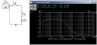
Sorry guys here is the actual rc network i added. But its not a question of time constant here its a matter of frequency response. Only when this network added that i get a good bass response as it attenuates the high frequency response by 6dB from the sym-a-sym5. Could it be due to the amplifier load interaction or some bias problem somewhere in the amp. Without this network there is excess high frequency response. This is not due to the load or the pre-amp they have been checked seperately and don't have this problem. Its with the amp.Can anyone help? Thanks
Sorry guys here is the actual rc network i added. But its not a question of time constant here its a matter of frequency response. Only when this network added that i get a good bass response as it attenuates the high frequency response by 6dB from the sym-a-sym5. Could it be due to the amplifier load interaction or some bias problem somewhere in the amp. Without this network there is excess high frequency response. This is not due to the load or the pre-amp they have been checked seperately and don't have this problem. Its with the amp.Can anyone help? Thanks
Attachments
Hi zeus_threat,
I would recheck your parts values used in your amplifier. I can only imagine that an error has been made. The amp design itself does not have this problem based on what the schematic looks like, and other reports from builders.
The main suspects would be the resistors and capacitors used in the feedback network and the input network as Andrew pointed out.
Bias current level may cause crossover distortion, but never a frequency dependant effect by itself. The output impedance is low enough to cause fuses to blow if it were an amplifier / load interaction.
AndrewT,
Thanks, but MikeB and Pavel are the experts on this amp!
-Chris
As i never had complaints about weak bass from symasym before, it's likely that there is an issue inside the amp...
Which version did you build, the latest ? Do you have two channels behaving the same or one prototype ? As Chris already told, have a look at the 470uF in the feedbackpath. If it's defect the paralell 100nf would do the job and kill all lower freqs.
That's a measured freq-response from symasym: (dominated by measuring setup)
Mike
Freq response Measurements
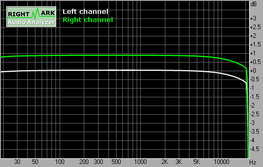
Well all that has been mentionned has been checked. Thanks to your previous post mike i found an easy to measure the freq. response using rmaa. I have only 1 prototype. I fed the left out of my sound card to the amp input and sent the amp output to the left line in of the s.card. Taking care of course not to fry it. Attached is the freq response measurement. Its still not giving me a clue as to why am not getting any good bass from this amp. The speaker has been tested with a yamaha AVX496 amp(with all tone controls neutral) and works fine. But the tweeter is playing too loud with my protoype. I even plugged a headphone into my soundcard(SBLIVE5.1) and then plugged it into the prototype's output but there was a clear rise in high freq response from the amp. Any help would be welcome.
Well all that has been mentionned has been checked. Thanks to your previous post mike i found an easy to measure the freq. response using rmaa. I have only 1 prototype. I fed the left out of my sound card to the amp input and sent the amp output to the left line in of the s.card. Taking care of course not to fry it. Attached is the freq response measurement. Its still not giving me a clue as to why am not getting any good bass from this amp. The speaker has been tested with a yamaha AVX496 amp(with all tone controls neutral) and works fine. But the tweeter is playing too loud with my protoype. I even plugged a headphone into my soundcard(SBLIVE5.1) and then plugged it into the prototype's output but there was a clear rise in high freq response from the amp. Any help would be welcome.
Attachments
Hi zeus, this freq response is definitely a disaster, it must sound worst.
Symasyms freq response is definitely flat, have you checked for cold soldering ? Another possibility would be that it is oscillating...
The most amazing is that the response falls that steep above 10khz.
Have you checked if biasing is normal ? Start with the voltages across the 2 680 ohms (r5/6). These should read both ~1v. Also important are r15/17 (150ohms), these should read both ~375mv.
Have you double checked component values ? (especially caps) Maybe you got the pinout of one of the small signal transistors wrong ?
Mike
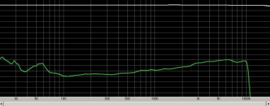
Ah, that looks different... Can you show freq response only, giving a better scale ? There seems to be a peak at ~1.5khz.
Btw, clicking on the disc icon gives you the option to save the spectrum as png file, beeing much smaller and better quality.
You might also have a problem with your powersupply...
Mike
Btw, clicking on the disc icon gives you the option to save the spectrum as png file, beeing much smaller and better quality.
You might also have a problem with your powersupply...
Mike
Listening test
Hi mike, well i have not yet run the test you mentionned i'll go ahed with it and post it. But i did something else in meantime. I tested the same speaker with a TDA7294 amp and the bass was weaker than the sym-a-sym5 prototype. Actually i've built the sym-a-sym5 prototype on veroboard but taking care to eliminate all unecessary tracks. The output transistors have been soldered directly to the board. Could the use of veroboard be the source of the problem or the fact i soldered the output trans. directly to the board or none of them? I've adjusted the bias to 15mA per resistor.
Hi mike, well i have not yet run the test you mentionned i'll go ahed with it and post it. But i did something else in meantime. I tested the same speaker with a TDA7294 amp and the bass was weaker than the sym-a-sym5 prototype. Actually i've built the sym-a-sym5 prototype on veroboard but taking care to eliminate all unecessary tracks. The output transistors have been soldered directly to the board. Could the use of veroboard be the source of the problem or the fact i soldered the output trans. directly to the board or none of them? I've adjusted the bias to 15mA per resistor.
Hi Zeus, as far as i know the TDA7294 is a high end chip amp, and as the symasym already shows better bass performance i guess your prototype is functioning correct. Of course the veroboard will degrade quality, hard to say how and how much. It's likely to add many distortions and give a crisp sound. Symasym is sensitive to layout because of the high open loop gain. My amps sounded on PCB always better than on test board. (not veroboard, soldered)
Did you drive the TDA7294 with the same power supply ? Maybe your power supply is simply to weak, or your Yamaha is boomy ?
What is your power supply ? You could try to omit the 2 1000uF caps (and the 100nf paralell) It's possible that you have a resonance between these caps and inductance from the supply.
What did you use as output devices ?
With 15ma bias, did you mean the outputstage ? That would be way too low, giving audible cross over distortion. You need at least 50ma.
One interesting check would be to measure frequency response with the speaker connected.
Mike
Thanks for the tips mike
Hi mike thanks for the answer. Regarding the frequency response. I tested it with an 8ohm loudspeaker but the wasn't any vibisible on the bode plot. Actually i have omitted the 1000uF and 100nF PSU bypass caps but its still the same. I'll try another PSU using with a greater current capacity, increase the bias current and report about the results
Hi mike thanks for the answer. Regarding the frequency response. I tested it with an 8ohm loudspeaker but the wasn't any vibisible on the bode plot. Actually i have omitted the 1000uF and 100nF PSU bypass caps but its still the same. I'll try another PSU using with a greater current capacity, increase the bias current and report about the results
Hi zeus_threat,
I doubt the headphones presented the amp with enough of a load to force it out of class AB and into class B. Crossover distortion would be visable on an oscilloscope, certainly with a THD meter (look at the residual).
Try a 330 R, 2 W resistor in series with the speaker output and with a 100 R resistor to ground in parallel with your headphones (in case you have high impedance headphones).
It would be interesting to know what you are hearing.
-Chris
Hi zeus (is that your name ?), have you already set the bias in the outputstage to 50ma ?
But, as Chris already pointed out, the headphone should not put enough load to the amp to enter ClassB.
Hiss from a symasym ? I suggest you etch some boards, it's very likely that you have layout issues, these can even cause oscillation.
For a test, you might add at least 47ohm emitter resistors to the diffamp (q1/q2). This gives plenty of safety margin against oscillation.
All builders mentioned how silent symasym is, there really should be no hiss.
What transistors did you use and did you exactly build as the schematic shown ? For example, skipping r8/r9 causes the outputstage to oscillate with ~30mhz.
If you use slow output transistors you must increase the bias above 100ma in the outputstage or you get audible distortions for higher freqs. (My experience with MJL21195/6)
Mike
- Status
- This old topic is closed. If you want to reopen this topic, contact a moderator using the "Report Post" button.
- Home
- Amplifiers
- Solid State
- Amp-Load interaction