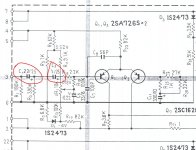
I've seen this done on any number of Pioneer amps and receivers from the 70's...one cap right after the other at the input to the power amp differential...
I can't for the life of me think of why...and I can't think of why the second cap (the 1µf) shouldn't simply be replaced with a wire...
I can't for the life of me think of why...and I can't think of why the second cap (the 1µf) shouldn't simply be replaced with a wire...
Attachments
Not just Pioneer, see the NAD3020 input. Note the "LAB IN", which gives a much wider bandwidth, is perhaps more conventional today.
In those days rumble and wow & flutter were things to fear.
In those days rumble and wow & flutter were things to fear.
I think ( I may be wrong...) that is because in both schematics shown the capacitors being used are polarized electrolytics and their intention was connecting two of them back to back to have a non-polarized one.
The resistors connected in between them are DC polarization resistors to try to compensate the characteristics of these capacitors.
João Pedro
The resistors connected in between them are DC polarization resistors to try to compensate the characteristics of these capacitors.
João Pedro
Joao,
It could be but the two caps are not "back-to-back" but in the same "direction", so I think that is not it. But then again, often you see errors in the schematic so the caps may in reality well be back-to-back.
The DC circuitry is to set the DC balance/ output offset. What is true is that if the 2nd cap is replaced by a short, the 390k resistor to the left upsets the balance circuit, but I find it improbable that this would be a problem, and they could always cut out the 390k.
Jan Didden
C1-R3 HP filter to block DC.
C3 is blocking DC from differential stage to enter first filter (C1-R3).
Bypass C3 would upset DC biasing to Q1. As it is in diagram the only DC connection to Q1 base is through R19 and on to DC balance pot. Bypassing of C3 will mean another additional DC path through R15 an R3 and seriously affect currents in differential stage.
Of cource replace caps with better ones doesn't hurt.
4fun said:C1-R3 HP filter to block DC.
C3 is blocking DC from differential stage to enter first filter (C1-R3).
Bypass C3 would upset DC biasing to Q1. As it is in diagram the only DC connection to Q1 base is through R19 and on to DC balance pot. Bypassing of C3 will mean another additional DC path through R15 an R3 and seriously affect currents in differential stage.
Of cource replace caps with better ones doesn't hurt.
That's what I thought but then again how serious can the upsetting be with an additional 390k resistor given the much lower resistances in the DC setting cirrcuit? Only minor, not enough to warrant an extra elcap. And that 390k can be jettisoned without problems anyway if the C is shorted.
Jan Didden
cpemma said:Not just Pioneer, see the NAD3020 input. Note the "LAB IN", which gives a much wider bandwidth, is perhaps more conventional today.
In those days rumble and wow & flutter were things to fear.
The NAD 2030 (and rest of the series) input is a completely different case. Look where the resistor between the caps goes, as well as the cap between the two series connected resistors that follow. This is an implementation of an active multiple feedback filter, the first section filters out subsonic, the secind, supersonic input. The 'lab in' input skips over the filter network, hence wider bandwidth.
Regarding the Pioneer, to be perfectly honest I don't see a reason for it other than doing a second order filter.
janneman said:
That's what I thought but then again how serious can the upsetting be with an additional 390k resistor given the much lower resistances in the DC setting cirrcuit? Only minor, not enough to warrant an extra elcap. And that 390k can be jettisoned without problems anyway if the C is shorted.
Jan Didden
R19 provide DC with Ri of greater than 100K, parallell 390K to ground will down Ri to 80K and make adjustments on VR1 less effective and non linear (R3 reference to ground). But it may work if adjustments of VR1 reach long.
I appreciate the input...just seems to add another cap to the signal path unnecessarilly. There are a fair number of Pioneer amps and receivers from the late 70's that use this type of configuration at the input, and I could not see a logical reason why...
The board is too tough to get to for experimentation, so I'll likely leave the current configuration as it is and install new caps.
The board is too tough to get to for experimentation, so I'll likely leave the current configuration as it is and install new caps.
- Status
- This old topic is closed. If you want to reopen this topic, contact a moderator using the "Report Post" button.
- Home
- Amplifiers
- Solid State
- Why did Pioneer do this?