Hi,
I am making the Maplin 150W MOSFET modules as a quick, cheap and dirty power amp.
Thing is my transformer is too high a voltage (+/-63vDC after rectifier) and is going to need regulting to the +/- 40v i will feed my modules with.
I have a nice big heatsink to mount my pass transistors on and have 4x flat pack 2N3055's on hand which i would like to use to drop the volatage.
I can make a circuit for the +ve rail regulator straight out of the art of electronics reference book, but i am not sure how to make a negative rail regultor using my NPN transistors?
How should i go about this?
Regards
Craig
You can't without using at least a PNP driver.
Although I would strongly advise you to abandon the idea of regulating such a huge voltage difference. You will probably need 3x as many pass transistors as you have, and the heat generated will be tremendous.
I'm pretty sure the original spec was about 60V rails anyway.
If you insist on 40V rails, I would urge you to simply obtain another more suitable transformer from a surplus shop or eBay.
How big is big? at 150W into 8 ohms output, you'll burn about 100W in each rail's regulator. Take a look at what people are using for Aleph 30s for comparison. Of course, if this is just for home use and you won't use that much power continuously, you can get away with less heat sink. Just remember you are thermally limited.
You also need to take a look at the SOA (Safe Operating Area) of your pass devices and figure the temperature on the sinks. You may find that you need to use all four of your 3055s on the positive rail.
Keeping with the quick and dirty concept, consider modifying the circuit to operate on your 63V rails or getting a 25VAC transformer rather than go nuts with regulation.
The rails will likely come down to less than 60 loaded with your current transformer, but plan voltage ratings around the peak. Ensure caps are rated for 80V or better, check dissipation in all resistors and front end transistors and double up the output devices (or triple). Be sure to use source resistors either 0R33 or 0R47 if you add more outputs. Each MOSFET needs its own gate stopper resistor as close to the device as practical.
It's really not that hard and a good learning experience. I may be more adventuresome than most, but my second amp project was modifying a Pass A75 with rails 15V higher than the design point. I had a few problems, but they were related to sloppy assembly not the rail voltages.
Thanks richie00boy, true it would be better to get a new transformer but this one fits perfectly in my case and is free ") !
!
These modules are designed for 50v max and i have heard they blow up easily when run at that voltage so 40V seemed a good supply.
say the transistors drop 20V at 2 amps thats only 40 watt per transistor, this is ok and within SOA i would guess since these devices are capable of 10A.
Since i have 4 of them could i not // them up for even better current handling ( 2 per supply rail)?
Regards
Craig
!These modules are designed for 50v max and i have heard they blow up easily when run at that voltage so 40V seemed a good supply.
say the transistors drop 20V at 2 amps thats only 40 watt per transistor, this is ok and within SOA i would guess since these devices are capable of 10A.
Since i have 4 of them could i not // them up for even better current handling ( 2 per supply rail)?
Regards
Craig
BobEllis, I would stack the MOSFETS up on top of each other to increase voltage handling if i had enough but they are fairly rare now and i only have 3 pairs.
I guess 2 amps was a bit conservative in my last post, more like 3 amps at max output (60w per device) ( i wont be using 4 ohm loads only 8 ohm) i guess the amp will be limited to more like 80 watts on a 40v rail.
The heatsink is pretty big, it used to cool 2 STK chips on a 80wx2 amplifier and i will have 2 fans blowing right through the fins and out the bottom of the case.
I do have smaller PNP type transistors that can drive my -ve rail 2N3055's so this is not an issue, just my pass transistors are all NPN.
Craig
Craig,
The build manual for the Maplin amp lists +/- 55v max in the specification but the write-up says Maplin’s recommended transformer will generate a supply of 55v to 58v. FWIW, my pair of Maplin 150W modules have been running for years with +/-56v supplies.
I also think it would be better to use a different transformer but if you want to use the regulator circuit, I’d recommend a darlington with the NPN/PNP power transistors to increase the current gain.
Nice one,
David.
I see, thats encouraging if i dont go too bold and hit the modules with 50V as opposed to 58/55V then the pass transistors will only dissipate about 30W at 3 amps which is easily accomodable (is that a word?) on my heatsink.
Nice tip on the Darlington, hadn't thought of that, i might be able to get away with some weak T0-92 type drivers that way.
Ill fiddle with the circuit i found in Horowitz and Hill and see if i can make it work for negative rails with PNP driver.
Many Thanks
Craig
Nice tip on the Darlington, hadn't thought of that, i might be able to get away with some weak T0-92 type drivers that way.
Ill fiddle with the circuit i found in Horowitz and Hill and see if i can make it work for negative rails with PNP driver.
Many Thanks
Craig
richie00boy said:I'm pretty sure the original spec was about 60V rails anyway.
The rails are a nominal +/-55V to +/-58V with strong warnings not to go over that. 100W into 8R, 150W to 4R. Maplin did a 39-0-39V transformer for it.
I'm not sure what the limiters were, but electrolytics in the kit were only 63V so maybe them.
Hi,
what does 150W mean?
1. 150W into 8ohms?
or
2. 150W into 4ohms?
or
3. 150W equivalent into 8r but rated to drive any 8ohm speaker?
If you are sure you will never use 4ohm speakers and/or 4 to 8ohm speakers then you will be quite safe using +-50Vrails to get 90W into 8r and could go to +-55Vrails to get 120W into 8r
Is your transformer dual secondary? If so then it is easy peasy...simply make two, identical and completely separate npn regulated supplies, one from each secondary. Then simply wire them in series (so one's neg is connected to ther other's pos as the gound point).
Trust me, the wee electrons 'll never know the difference.
Trust me, the wee electrons 'll never know the difference.
Traderbam, I think i know what you mean.. thats a nice idea this would eliminate the need for an NPN driver for the negative supply regultor.
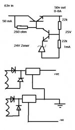
I have made a diagram of my proposed regulator circuit and have added a diagram of what i thought you were saying in your transformer wiring post.
If you could check it out for me id be grateful as using all NPN's makes it a little simpler to design.
Do my values look correct for the upper transistor regulated circuit?
PS. the pass transistor is a darlington not the single transistor as indicated in my diagram.
Cheers
Craig
Attachments
Craig,
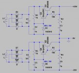
Yes, that is what I meant. I've attached the sort of circuit I had in mind. This is simple, cheap and will behave itself.
The 2N3055s are beefy but slow so the R2-C3 are needed to smooth the output impedance at high frequencies. C3 should be rated at 63V or more. C2 should be reated at 50V or more. Use 1W resistors for R1 and R2 and a 1W zener. I'm not sure what transistors you have so I chose an MJE243 for Q3. Let me know what you'd want to use here.
To get more sophisticated will take more parts and careful design because you'll need a feedback system. I am happy to help if you wish to go this way. I think your Maplin modules will sound fine with this circuit.
BAM
Attachments
Hot stuff  Well the regulator has half the V across it as the amp, but it is constant V, so the regulator will probably end up dissipating about the same power that the amp does in heavy use. I haven't done the maths so that's an educated guess. Provided everything is stuck on a big heatsink it'll be ok. It's a lot less effort to use the right transformer...but costly.
Well the regulator has half the V across it as the amp, but it is constant V, so the regulator will probably end up dissipating about the same power that the amp does in heavy use. I haven't done the maths so that's an educated guess. Provided everything is stuck on a big heatsink it'll be ok. It's a lot less effort to use the right transformer...but costly.- Status
- This old topic is closed. If you want to reopen this topic, contact a moderator using the "Report Post" button.
- Home
- Amplifiers
- Solid State
- Maplin 150w MOSFET regulation?