cyrus 2 capacitor
hi
is the capacitor i have linked to below the required type
http://www.maplin.co.uk/Module.aspx?ModuleNo=23074&criteria=capacitors&doy=18m5
just to make sure i have the right one.
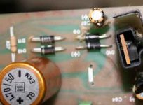
I have a pic of the underside attached and as you said there is a + sign so side closest to edge is positive.
Thanks for the help
hi
is the capacitor i have linked to below the required type
http://www.maplin.co.uk/Module.aspx?ModuleNo=23074&criteria=capacitors&doy=18m5
just to make sure i have the right one.
I have a pic of the underside attached and as you said there is a + sign so side closest to edge is positive.
Thanks for the help
Attachments
The track breaking points to another fault as well as the cap. Really you need to trace where the track connects to. This is where the schematic comes in handy. If you tell me if you have issue 6 design (pushbutton mains switch), or issue 7 (toggle mains switch) I can put the appropriate schematic up.
Can't really coment on the cap, need to check the pin spacing.
Can't really coment on the cap, need to check the pin spacing.
Re: cyrus 2 capacitor
No, far too large! 4700uF rather than the required 470uF.
Try this page instead:
http://www.maplin.co.uk/Module.aspx?ModuleNo=11992&&source=14&doy=18m5
You will probably need to go for the 470uF 100V to get the right lead pitch.
atomised said:hi
is the capacitor i have linked to below the required type
http://www.maplin.co.uk/Module.aspx?ModuleNo=23074&criteria=capacitors&doy=18m5
just to make sure i have the right one.
No, far too large! 4700uF rather than the required 470uF.
Try this page instead:
http://www.maplin.co.uk/Module.aspx?ModuleNo=11992&&source=14&doy=18m5
You will probably need to go for the 470uF 100V to get the right lead pitch.
Hi atomised,
I've seen that trace go on other Cyrus 1 products.
Please check for a shorted diode, that would explain the exploded cap as well. A 63 V capacitor should be close enough in pin spacing. That is the value I use for replacement. Use a piece of insulated wire to replace the burned track, cut away all the loose trace.
Any short in the supply from that capacitor could also cause the burned trace. Do not fail to replace the 22 uF caps (I thought they were 10 uF - sorry) and replacement of the regulators may not be a bad idea. I know they were running hot (they all do).
That should put you back in fighting trim.
-Chris
anatech said:A 63 V capacitor should be close enough in pin spacing.
Chris
Sorry to disagree with you but modern 50V and 63V 470uF capacitors have a lead pitch of 5mm. The older 16mm dia cans used in the Cyrus 1/2 have a lead pitch of 7.5mm which is why I suggested atomised went for a 470uF 100V which also has a lead pitch of 7.5mm.
That is of course assuming that one wishes to match the lead pitch rather than splaying the leads and mounting the capacitors further off the board.
Geoff
The burned broken track routs both caps to the star ground (which is between the main power caps), so it is very likely one of the diodes (close to the cap) broken also. The orientation of the cap is - maybe already mentioned - with plus outwards. Both caps should be changed, that is pretty obvious.
An Cyrus 1 from this bunch (small transistors) can easy be changed into a Cyrus 2 (power amp only) by adding another 4 output transistors, adding another 4 drivers (ZTX753/653), all other parts are on the board already. I forgot the infos about the bigger transformer.
I did not remember a sensational big difference in sound to a Cyrus 1, but I only have one Cyrus 1 left in my collection.
Hi Geoff,
I form the leads with bent pliers. A touch of silicone will stabilize the cap. I see nothing wrong with this approach.
Splaying the leads is a fairly low tech approach, but it works as long as the leads aren't under tension near the seal. Doesn't look good though.
To each his own. I don't happen to stock 100V, I go to 250V and up from there. I refuse to put in another skew so I don't have to bend the leads.
-Chris")
I form the leads with bent pliers. A touch of silicone will stabilize the cap. I see nothing wrong with this approach.
Splaying the leads is a fairly low tech approach, but it works as long as the leads aren't under tension near the seal. Doesn't look good though.
To each his own. I don't happen to stock 100V, I go to 250V and up from there. I refuse to put in another skew so I don't have to bend the leads.
-Chris
TroelsM said:Hi.
Having just a quick glance at the Cyrus schematic it strikes me that it's a good candidate to a simple, cheap DIY-amp.
The schematic contains some (at least to me..) "new" elements and the output-transistors are dirtcheap.
Any Ideas?
Regards TroelsM
I wouldn't call the amp simple, cheap DIY. Yes it's DIYable but I would say it's more for the experienced constructor. My definition of simple and cheap is ESP P3a.
AndrewT said:Hi Troelsm,
the semi latching protection monitoring the Re(output) current is a nice touch. I have referred to it in other threads.
I don't know what the protection sounds like!
Has anyone found similar in other amps?
Anatech,
I thought I said in post10.
Well funnily enough I removed the protection from my friends amp. It obviously doesn't function very well as the amp was broken by shorted speaker leads - output devices and drivers were taken out.
I also used MOSFETs instead of BJT outputs and modded the Vbe multiplier to suit, but that's another story
Hi Richie.
As far as i understand very few amps, will tolerate a hard short at the output terminals, - at least if there's any signal present.
I haven't simulated this particular protection-circuit, but maybe it's not designed to protect the amp in case of a hard short for a longer period of time.
Regards TroelsM
Hi mc square,
They are in fact bipolar capacitors. Mighty small ones too.
The problem some of those caps have is that they go open. This results in no bass, or more severely, greatly reduced gain. At the voltages those caps are exposed to you can use a polarized unit.
-Chris
They are in fact bipolar capacitors. Mighty small ones too.
The problem some of those caps have is that they go open. This results in no bass, or more severely, greatly reduced gain. At the voltages those caps are exposed to you can use a polarized unit.
-Chris
- Status
- This old topic is closed. If you want to reopen this topic, contact a moderator using the "Report Post" button.
- Home
- Amplifiers
- Solid State
- cyrus 2