Dear members of this forum,
this is my first thread.
I found in the web some interesting japanese amp-designs.
http://www.geocities.jp/mutsu562000/
One of them seems to me very attractive because it is well dokumentated too.
Could somebody take a look at it and give me some advice about expected power, oe even it is easy or difficult to build?
http://www.geocities.jp/mutsu562000/root/amps1/htm/e/hp037e.htm
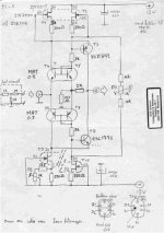
I have attached the schematic of the amp
Thank you very much
Sam
this is my first thread.
I found in the web some interesting japanese amp-designs.
http://www.geocities.jp/mutsu562000/
One of them seems to me very attractive because it is well dokumentated too.
Could somebody take a look at it and give me some advice about expected power, oe even it is easy or difficult to build?
http://www.geocities.jp/mutsu562000/root/amps1/htm/e/hp037e.htm
I have attached the schematic of the amp
Thank you very much
Sam
Attachments
Probably this positive current feedback network just lowers output impedance but still keeps it positive, with higher open loop gain it would be possible to go negative. 330mA for +-27V rails in class A single ended makes completely no sense and nearly zero efficiecy. I would go for something like +-10V and 1A to possibly call it 'power' amplifier.
Masag, leave it. It is nonsense and a lesson taken from it should be 'never trust transistor beta'.
cheers
Masag, leave it. It is nonsense and a lesson taken from it should be 'never trust transistor beta'.
cheers
Thank you very much, for your fast replay!
Maybe I should try your amp Mike?
What's about that design? I t is on the same website?
http://www.geocities.jp/mutsu562000/root/amps1/htm/e/hp179e.htm
Maybe I should try your amp Mike?
What's about that design? I t is on the same website?
http://www.geocities.jp/mutsu562000/root/amps1/htm/e/hp179e.htm
Attachments
This last one is the Kaneda Full Symmetry design, which was first published some 20 years ago. There have been many many different versions built, including Power JFETs, all MOSFETs, UHC-MOSFETs, .... both in Class A ans Class AB. You can even buy a book from Kaneda on Amazon.co.jp that gives full instructions how to build one (in Japanese). No PCBs, all point-to-point wiring. Beautiful craftmanship.
The ISBN number of the book is 4-416-10405-7 @ 3200 Yen.
Amongst others, you need to match all transistors; and you need to know how the circuit works. I am sure there are enough experienced builder here who can give it a go.
Patrick
The ISBN number of the book is 4-416-10405-7 @ 3200 Yen.
Amongst others, you need to match all transistors; and you need to know how the circuit works. I am sure there are enough experienced builder here who can give it a go.
Patrick
masag, your last shown looks quite good, if i am right you will need lateral mosfets to have it thermal stable.
If you try mine you have the advantage that you can order all parts necessary at once at www.reichelt.de except the mpsa18 and outputdevices maybe.
Mike
If you try mine you have the advantage that you can order all parts necessary at once at www.reichelt.de except the mpsa18 and outputdevices maybe.
Mike
> if i am right you will need lateral mosfets to have it thermal stable.
Not necessarily.
As I mentioned, there are all sorts of versions being built in Japan with different output device types, including bipolar.
In addition, the 150R resistor shown at the drain of the second diff pair is a temperature dependent device (if I am not wrong NTC) to be mounted close to the Power FETs for temperature compensation.
And in my own experience, Toshiba 2SK1529, e.g., has negative temperature coefficient at bias < 1.3A (Vds up to 25V), and would be fine in that circuit with minor modifications.
Patrick
Patrick,
thank you very much for the information.
I am going to order the two books.(there is an english language site).
What modifications do you think, I have to do, using 2SK1529?
Must I match the 2SA606 too?
Next question, does anybody know a source for Copal wirewound trimmers (typ1113)? They are working fine for years in my Monster and Kaneda preamp.
Mike,
your amp is on top of my list.
Kindest regards
Sam
Sam,
I stress this is pure personal opinion :
I would change the driver MOSFETs to 2SK1529 (because I have lots), bias them at around 1.2A Class A. This means that you want about 3.5V Vgs. If you were to bias the 2SA606s to say 7mA, then you would need to change the top resistor (currently 1k trimmer) to about 250R nominal. So I would use a 500R trimmer. Then the collector resistors (currently 150R + 100R in series) would want to be about 500R. You can drive up to 3 pairs of 2SK1529s and still have high bandwidth there. And that would get you 3.6A pure Class A bias. I would use about 400R gate stopper resistors per FET (currently none), probably more if you use only 1 pair of 2SK1529. This you would need to experiment, to get stability.
But this is only personal taste. Others might want to operate the circuit at different values. And you might want to use other FETs such as 2SK1530, IRFP240, IRFP044, .... etc.
And yes, I would match the 2SA606s for hfe as well, but then I personally would use MOSFETs there (e.g. ZVP3310A). Again a matter of taste. JFETs would have been fine as well, if you can fine some low noise ones that would survive 60V Vgs. Of course you can also use monolithic matched pairs, such as SSM2220, or MAT03. Many many options possible.
For the first diff pair, 2SK170 is fine, but if you can get 2SK389 (or LSK389), that saves you matching.
Patrick
Sam,
When you have the books, try to read through Chapter 2 of Book1. Especially Fig. 106 (P.71) is a good circuit to start with. And this is original Kaneda.
The high power version is described in chapter 9 of book 2.
The circuit you attached is probably not his original but done by someone else based on the same topology.
Patrick
Hi Sam,
Here is a good site for Akihito Kaneda's projects, in Japanese. The site is a bit less organised than norm so be patient. The second button from the left panel will link you to the projects.
http://www.sm.rim.or.jp/~konton/
Regards
Max
Here is a good site for Akihito Kaneda's projects, in Japanese. The site is a bit less organised than norm so be patient. The second button from the left panel will link you to the projects.
http://www.sm.rim.or.jp/~konton/
Regards
Max
Sorry for my late replay, was out for one day.
Max,
thanks for the link to the Kaneda projects, in deed it is a little confusing, and some parts a really not available any more f.e. FD1840
Patrick,
thank you very much for your detailed advice specially to the transistor substitudes.
MAT02/03 are hard to find in Germany. I think Elektor has used them in some amp designs.
Can you compare the SSM2220/10 with them?
Here is a MC headamp schematics, I want to start now, so the help you send to me came just in time.
I have found the pix inan older thread
Thanks and regards
Sam
Attachments
> MAT02/03 are hard to find in Germany.
Not true. Available from www.reichelt.de. Just cost a few Euros extra.
> Can you compare the SSM2220/10 with them?
For me they are the same stuff in different packages. Just compare the data sheets from Analog Device.
I have no problems using SSM2220 in my X'ed JLH. But I also have had MAT's before.
Patrick
> would tell me more of your JLH amp, link to the schematics?
http://www.diyaudio.com/forums/showthread.php?postid=658958#post658958
If you send me a email, I can send you some photos.
Patrick
http://www.diyaudio.com/forums/showthread.php?postid=658958#post658958
If you send me a email, I can send you some photos.
Patrick
- Status
- This old topic is closed. If you want to reopen this topic, contact a moderator using the "Report Post" button.
- Home
- Amplifiers
- Solid State
- Japanese amp design