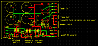
This is my stab at making a +/- 12 volt power supply. There is a ground plane on top which is not shown, also standoff holes not shown. The motivation is to get a third 12 volt output for relays. The right side of the board will be one array of screw connector terminals, the aux out must be shorted in order to power and unmute the relays. The aux out is fully regulated by design to be flexible. For simplicity, I will be adding a solid state ac controlled relay to control the aux out, but a proper trigger switch or other control circuit could easily be implemented.
A ground isolating network was used. Fusing is design to be flexible.
I placed all the regulators on one side of the board for easy cooling. Regulator capacitance is 100 uF electrolytic. All my opamps are bypassed with ceramic later.
Sources:
-sound.westhost.com
-www.adireaudio.com
-www.diyaudio.com
-www.national.com
-My terrible electrical engineering book which is the most useless thing ever, and I want to send the author hate mail
Attachments
A few things that I have learnt along the way from cleverer people than me.
The traces to the big caps should run directly to their pins with the thickest track you can get away with, and then from them the tracks should then get slightly smaller to run to the regulators. In fact, all the traces could be thicker than you have.
Don't worry about a ground plane, just get a nice star ground set up instead. Think where the currents are flowing, and try and keep the big ones away from the small.
Try and arrange your PCB so all the + terminals of the elcaps point in the same direction. It makes troubleshooting a lot easier.
The regs will work better if you have 0.1uf film caps bypasing the input rails.
Oh, and I hate non isometric tracks in PCB layouts!")
The traces to the big caps should run directly to their pins with the thickest track you can get away with, and then from them the tracks should then get slightly smaller to run to the regulators. In fact, all the traces could be thicker than you have.
Don't worry about a ground plane, just get a nice star ground set up instead. Think where the currents are flowing, and try and keep the big ones away from the small.
Try and arrange your PCB so all the + terminals of the elcaps point in the same direction. It makes troubleshooting a lot easier.
The regs will work better if you have 0.1uf film caps bypasing the input rails.
Oh, and I hate non isometric tracks in PCB layouts!
Hi
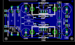
1) Traces from C3 should run directly to C2's terminals (2pl)
also ground plane connection conn close to C2 terminals.
reason- isolate high current noisy traces i.e. rectifiers to big caps to minimize noise coupling to pass transitor inputs.
2) Don't use ground plane over high current noise traces same reason as 1).
3) Up date reference designators ( some repeats) reason- all components on same pcb should be unique.
Hi
replace my last post with this (edit timed out)
1) Traces from C3 should run directly to C2's terminals (2pl).
In addition ground connection conn close to C2 terminals.
Reason- isolate high current noisy traces i.e. rectifiers to big caps to minimize noise coupling to 3-T regs inputs and ground out.
2) Don't use ground plane over high current noise traces same reasons as 1). and capacitive coupling thru bottom to top into ground plane.
3) Run high current noisey traces from one big cap then to last one C2 not in between them. Also run these traces parallel to keep the loop area small. Mimics twisted wire. Don't really need fat traces if you know where to pick off traces.
4) Update reference designators. ( some repeats) Reason- all components on same pcb should be unique.
Agree with Pinkmouse on this. You don't really need a ground plane on this board, can actually cause more harm than good. Point to point is better for filters and regs.
I want one when you're finished! For active filter PCB Group Buy?
Thanks for the tips, I will be working on this more after I get more "real work" done.
"I want one when you're finished! For active filter PCB Group Buy?"
That's the idea in general, active filters are popular here these days. The other group buy power supply is probably a better design, but an aux out would be handy, as well as some decisions that make wiring it up easier for me at least.
mazurek said:The other group buy power supply is probably a better design, but an aux out would be handy, as well as some decisions that make wiring it up easier for me at least.
Maybe a better design or just different objectives and tradoffs like any thing "beauty in is the eye of the beholder". Have you thought of using a more flexible 3 term adjustable regulator. The noise performance is much better than fixed.
P.S. Like to hear more on your muting concepts. I have a simple idea of using a 24V relay coil sensing the +/- 12 V supplies with its NC contacts shorting the outputs of the active filters outputs.
Hi,
The two C3a, C3b need to be very close to the input pins of the respective regulators. I really mean very close, even mounted on the back of the pcb direct to the reg pins. Similarly the output pins can benefit from close coupling the cap bypasses.
If you change to 317/337 types the close coupling seems to be slightly less important but still worth doing.
are these the C3 that appear on your layout?The regs will work better if you have 0.1uf film caps bypasing the input rails
The two C3a, C3b need to be very close to the input pins of the respective regulators. I really mean very close, even mounted on the back of the pcb direct to the reg pins. Similarly the output pins can benefit from close coupling the cap bypasses.
If you change to 317/337 types the close coupling seems to be slightly less important but still worth doing.
infinia said:
Have you thought of using a more flexible 3 term adjustable regulator. The noise performance is much better than fixed.
P.S. Like to hear more on your muting concepts. I have a simple idea of using a 24V relay coil sensing the +/- 12 V supplies with its NC contacts shorting the outputs of the active filters outputs.
I thought about the adjustable regulators, if its a good idea, I'll use them. I originally was using them in my pcb design, but got annoyed at the amount of space it takes to put in a potentiometer. Would it be ok for your use to put them in and use a fixed resistor network? I suppose that AndrewT's comment about capacitor proximity on the lm317 might mean there is more room to play with around the regulators.
I was basing a lot of the relay stuff on Rod Elliot's comments in his P05A project. Supposedly the relays can add noise into a regulated power supply when operating, if this is true, could maybe fix it with some diodes and capacitors. The other factor would be ensuring that they cut off in time. The relays I'm using have a 10% min dropout voltage, and 5ms must release time. I suppose you could play with your supply capacitance until the relays open before you hear voltage drop. I don't have gear detailed enough to measure what part of the voltage drop yields the most audible pop. I was thinking a regulator for the relays is a good idea, because then you can have separate voltages for relays and opamps without adjusting some pot to get the voltage you want for the amount of relays you have.
AndrewT said:Hi,
are these the C3 that appear on your layout?
The two C3a, C3b need to be very close to the input pins of the respective regulators. I really mean very close, even mounted on the back of the pcb direct to the reg pins. Similarly the output pins can benefit from close coupling the cap bypasses.
If you change to 317/337 types the close coupling seems to be slightly less important but still worth doing.
Thanks for the suggestions, I'll work on fixing that. Right now I have a ceramic decoupling capacitor before the input as well as the electrolytic ones. Can I do with a C0G ceramic across the inputs instead of a film. Film capacitors are very large, and from the specs it seems that ceramic are better with HF anyhow? Or I could find room for both, I suppose the polystyrene capacitors are a little smaller than the polypropylen I was looking at.
By the way AndrewT, I know you told me earlier about how ground planes weren't always good, it was really a matter of my laziness that I used them on this (didn't want to spend the time drawing ground traces). I will fix it though.
mazurek said:
1) I thought about the adjustable regulators, Would it be ok for your use to put them in and use a fixed resistor network?
2) The relays I'm using have a 10% min dropout voltage, and 5ms must release time. I suppose you could play with your supply capacitance until the relays open before you hear voltage drop. I don't have gear detailed enough to measure what part of the voltage drop yields the most audible pop.
3) Right now I have a ceramic decoupling capacitor before the input as well as the electrolytic ones. Can I do with a C0G ceramic across the inputs instead of a film. Film capacitors are very large, and from the specs it seems that ceramic are better with HF anyhow? Or I could find room for both.
1) Pot's are very nice, but don't really need them here.
2) I expect opamps start to sound ugly around +/- 5V, but it depends on the particular ones used. I'm not sure about relay's causing noise or other issue's in steady state operation. For relay's with a tighter dropout, timing should not be a issue as long as they cutout/turn on above the opamps dropout voltage, they should be fine. If you want you can sense at Vreg input instead and use a suitable RC filter to get within relay coil specs.
YMMV
3) My sense around here "audiophile land" that caps that are really sticky issue for some people. Rightly or wrongly the "right"selection depends on their application. Some people unnecessarily avoid ceramics like the plague. C0G are really the best ceramics in lower values, but are too large and costly when values approach .01uF or greater. As you pointed out ceramics when used as supply bypasses (low impedance & low gain) are a better choice, even heaven forbid the X7R type. On the other hand I would not use them (X7R) in opamps filters or in the signal path (high gain/impedance). Again whatever floats your boat.
infinia said:
2) I expect opamps start to sound ugly around +/- 5V, but it depends on the particular ones used. I'm not sure about relay's causing noise or other issue's in steady state operation. For relay's with a tighter dropout, timing should not be a issue as long as they cutout/turn on above the opamps dropout voltage, they should be fine. If you want you can sense at Vreg input instead and use a suitable RC filter to get within relay coil specs.
YMMV
It seems to me to be a tradeoff, I agree I don't know how a relay could cause steady state (unless it induces oscillation when switched). With only two supply rails you save money on regulators, but you need better relays and a more application specific relay electrical network. My approach requires a more expensive power supply, but I'm able to use any number of $1.50 relays without tuning the electrical network (most 24v signal level relays I saw on digikey were 5 dollars a piece, and I'm using one relay per output). On the other hand, I also require a 17 dollar bipolar solid state relay for ac sensing, but I figure I could use this power supply to add a 555 timer or other cool trigger in/out features eventually (and make this stuff pro grade).
Also on the subject of relay muting etc, I believe I will try shorting the input also to prevent oscillation during power on transients (I realize I need to fix the feedback networks to make the circuit oscillation proof, but the only time it has ever oscillated was during startup transients). That combined with eventually putting in a 555 timer should make the circuit bullet proof I think.
I should have a revision out by tonight. Got to do my homework so I can keep my grad stipen though.
Hi,
ceramic bypass are smaller, cheaper and perform better than almost any other type when used on constant voltage power supplies. I would be surprised if styrene were smaller than propylene and both would be a waste of resources for bypass duty.
BTW min drop out voltage is the maximum voltage that guarantees that all of these models of relay WILL drop out.
The max drop out voltage is when the least sensitive start to drop out. This is the minimum voltage you need to ensure all these relays will hold in.
The 10% figure you quoted would be the min drop out. Max drop out is more likely to be 20% to 40%.
I think the figure you should be looking for in the spec is the max drop out voltage.
Thanks for the reply AndrewT. I'm still working on the new pcb, I'm putting ceramics right on the input and output.
For the muting relays, they are supposed to ground the output when the relays stop recieving power, so I would want to guarantee the normally open has contacted before the power has fully dropped. I think that would require a minimum power level threshold. The opposite way, mute when power is applied doesn't seem as robust.
For the muting relays, they are supposed to ground the output when the relays stop recieving power, so I would want to guarantee the normally open has contacted before the power has fully dropped. I think that would require a minimum power level threshold. The opposite way, mute when power is applied doesn't seem as robust.
infinia - for now I think I'm keeping the fixed regulator, I'm not sure I want to spend the time to put in the resistor network (busy week). But if you want, I can email you the file (I'll go in with yours if you can roll out changes quick, send me an email).
Any more tips? I would like to be able to build this this weekend.
Any more tips? I would like to be able to build this this weekend.
Hi Mazurek,
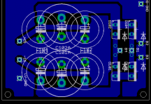
your caps C9,10 & C12,13 are not located at the pins of the regs. C9 has correct orientation but the common leg seems to have a very long route away from the ground pin. 0.1inch pitch ceramic are available (they will be the smallest component on the PCB).
Your two resistors are 0.4inch pitch, try 0.6inch or 0.7inch or at very least 0.5inch pitch. Similarly the diodes could be stretched a bit. Are they 1n4148 or 1n4002? It is not a good idea to bend the leads too close to the body
A 100nF across the AC1 and again across AC2 would help attenuate spikes before they enter your PSU.
Listen to Pinky. Star ground to minimise interaction of your ground references.
Here is part of a PSU I designed for a valve preamp. For this, I do use a ground plane, but note how if you trace current loops from the component pins back to the ground at the RH side of the board, they don't cross any other pins. Note also, that I didn't put an output ground on the PCB. It makes much more sense to run grounds from other pcbs back separately back to the main chassis star ground point. Does that help?
:edit: As with all pcb design, getting the component layout on the board correct is 90% of the battle.
:edit: As with all pcb design, getting the component layout on the board correct is 90% of the battle.
Attachments
I'll work on the star ground. Infinia suggested moving to one cap per rail, deleting the r2 resistor, and removing the protection diodes to free up lots of space. If I free up that much space, I can maybe have room for attachable heatsinks and put the plus and minus on opposite sides which might make this layout a lot easier to work with.
AndrewT:
You mean I have to put the caps closer yet, or is there another problem (do you mean I have to cap i and o to the g pin, or is any part of the ground good enough?). I think I'll switch to adjustable regs and share the design effort with infinia, if we switch, are the caps close enough?
The regulator diodes are 1n4002, do you agree that they are unnecessary, the datasheet really just says I need them if I have lots of output capacitance (others are rectron diodes recommended by adire power supply for ground isolation). I was going to go with about 100uf electrolytic (bypassed with the ceramic directly at the reg).
I'll add the 100nF cap at the ac inputs.
Pinkmouser:
Thanks for the schematics. I think if I rearrange the board and lose the requirement that both regs must be on the same side I will have much cleaner routing and grounding. I really like having the common output on the pcb, that way I can use a safe ground isolation network (d1,d2,c1,r1) on the pcb. I really hate floating grounds, and don't want a ground loop issue. As an aside, I've been measuring the impedence from signal gnd to chassis ground on all my real consumer devices to see how they deal with the issue. My adcom preamp uses 200 ohm resistor as far as I can tell.
- Status
- This old topic is closed. If you want to reopen this topic, contact a moderator using the "Report Post" button.
- Home
- Amplifiers
- Solid State
- active crossover power supply pcb check before making