This circuit will work. As shown, it will operate in class B so it will have crossover distortion thus sounding pretty bad.
You could take the 100 ohm resistor that is between the diode and the 3.3k resistor and change it to 390 ohms (based off simulation) or even put a potentiometer in there so you can adjust the bias.
You could take the 100 ohm resistor that is between the diode and the 3.3k resistor and change it to 390 ohms (based off simulation) or even put a potentiometer in there so you can adjust the bias.
sreten said:
Not for very long IMO,/sreten.
You mean, that most amps don't survive being thrown out of a window?

Sith,
for most of us the powersupply, heatsinks, and the case of an amplifier are the parts that cost the most to construct an amplifier.
And that's without counting the time you put into it.
The parts and pcb's of the amplifier circuit is a relative small part of the total cost, putting time and money in a crappy circuit is a waste.
My reaction to the circuit you posted is: Yikes !
If you are thinking of constructing an opamp entrance amplifier, there have been so many designs since the mid 1980s, why bother with something so horrible.
Even an LM or TDA chipamp module will be easier and sound better.
Just love your dry sense of humor, DarkFenriz.
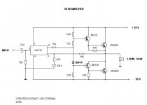
Hello, I saw this topic searching for something easy to build for unpretentious clients, so I don't lose my time in building good schematics for not so good listeners, so I decided to edit a little bit this easy circuit for some extra output power...
I would like it, if You people answer me some questions.
1. The 3k/2W resistors are calculated for 15mA current for the opamp is this enough ?
2.What output power will I get if I use my edited schematic on higher voltage than +/-45V with the MJ15003
3.What output power will I get with 2SC5200 on +/-35V and on +/-45V ? ? ?
I wait for your comments and recommodations...
Attachments
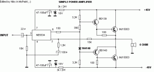
This will not increase a single watt as the voltageswing is determined by the opamp... Don't use fast trasistors with that simple circuits, it might bite you with oscillations.
If you need it simple and powerful go for a bootstrapped topology, similar to the p3a...
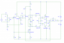
Or see attachment... (have not build that) You can use the sc5200/sa1943 as output.
Mike
If you need it simple and powerful go for a bootstrapped topology, similar to the p3a...
Or see attachment... (have not build that) You can use the sc5200/sa1943 as output.
Mike
Attachments
kalmara said:
Hello, I saw this topic searching for something easy to build for
unpretentious clients, so I don't lose my time in building good
schematics for not so good listeners, .....................................
I wait for your comments and recommodations...
http://sound.westhost.com/project19.htm
Simple, easy, 50W and almost completely idiot proof.
also see :
http://sound.westhost.com/project76.htm
/sreten.Hi!
Can only agree with all negative posts on the first suggested amplifier and the "improved" variant . Will be very unlinear before feedback leaving lots of correction job to opamp.
There are so many much better amps as already suggested in this thread, and they will sound much better.
Anders
Can only agree with all negative posts on the first suggested amplifier and the "improved" variant . Will be very unlinear before feedback leaving lots of correction job to opamp.
There are so many much better amps as already suggested in this thread, and they will sound much better.
Anders
- Status
- This old topic is closed. If you want to reopen this topic, contact a moderator using the "Report Post" button.
- Home
- Amplifiers
- Solid State
- strawa 50W