Is this in relation to my circuit? Eg post #34? Or is it more general? I'll assume it's more general.How about sensing the current separately as shown. Any benefits etc ?
One advantage of using a diff amp is less problem with hum. For the resistor sensing at the cold side of the speaker it needs to go to a true star point for other commons of the power amp along with the power supply caps, especially the second feedback resistor that goes to common.
When you use the diff amp one resistor to the +ve input goes to common and this can be terminated clear of the power supply center rail and power supply caps, so you are not forced to use a true star point anymore (which is very difficult if one power supply is common to 2 power amps).
On the down side, you need more parts and PC area for the diff-amp, precision resistors, you get some of the following: offset voltage and drift with temperature, noise, distortion, power supply noise, added phase shift when feeding the signal back to the power amp making compensation that bit harder.
Since the opamp rail voltage is less than the power amp output swing the input resistors need to attenuate to stay within the best common mode rejection region. Hence more of an issue with offset voltage, drift with temperature, noise, distortion.
But if star point hum is a problem then adding the opamp diff-amp can improve the power amp spec's.
BTW you can alternatively add a diff-amp to the resistor on the cold side to overcome the star ground hum problem. In this case you don't need attenuation for the diff-amp, so issues with offset voltage, drift with temperature, noise, distortion are reduced.
Originally Posted by IanHegglun
Is this in relation to my circuit? Eg post #34?
Yes ! I thought it "might" be a useful alternative approach.
All your points were helpful, & have been noted.
Looking forward as to how this IV Amp pans out
")
Hoping for a resistor and a voicecoil to thermally track seems like a finicky solution to me. For one, speakers which are designed to pump air at high excursions for cooling will have dynamically changing thermal constants.
I think a better way would be to measure DCV across the speaker and DC current to determine the actual voicecoil resistance.
10mV offset into 8 ohms is 1.25mA, seems reasonably within sensing range. In a Jfet input amp, the feedback DC lytic could be the sensing point for speaker offset. A Jfet or LDR could be used to vary gain to compensate for voicecoil resistance change.
True, but a thermally coupled resistor will probably be worse because thermal coupling not only has BW limitation but temporal delay. With a V/I sensing circuit you have complete control over the phase behavior and time constants and you can push them to the limit.
Also I shouldn't have said to compensate the compression by changing the gain. The correct method would be to use negative resistance to cancel the VC resistance, but not the reactance of the speaker. Although whether that is really best is debatable because if the voicecoil is hot enough to goof up the speaker, then who's to say the suspension is not all out of whack either?
Also I shouldn't have said to compensate the compression by changing the gain. The correct method would be to use negative resistance to cancel the VC resistance, but not the reactance of the speaker. Although whether that is really best is debatable because if the voicecoil is hot enough to goof up the speaker, then who's to say the suspension is not all out of whack either?
Last edited:
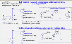
Voicecoil thermal model
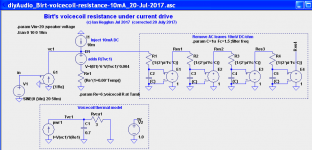
To show the response time of the Birt method of measuring the voice coil resistance using a 1mA DC bias I have first made a voice coil model with electrothermal feedback. In a following post I use this thermal model with a filter to remove 20Hz leaving the voice coil DC voltage for temperature reading to see how fast (or slow) it settles.
BTW Birt's original circuit was for operating from 300Hz so it did not need a high-order filter. But we want to filter from 20Hz for a full-range system.
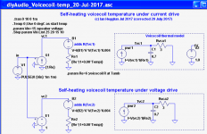
The attached circuit shows my thermal model to feed a current source (B1) that emulates a resistor which adds to resistor Re1 which is a fixed resistance at ambient.
I have used thermal model values from Zuccatti (JAES Jan 1990 p34) and neglected the other slow time constant (1000s for the heating of the magnet and yoke). The Zuccatti model is for a 130mm diameter speaker rated for 16W continuous sinewave power or 100W burst for 1 second.
I step input the voltage to a current source (the power amp) with 30V, 40V and 60V giving speaker power of 150W, 270W and 600W respectively.
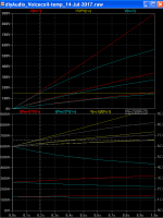
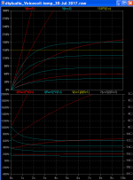
The yellow line shows the rated maximum temperature limit of 150C (Class-F). It is reached in 1 second with 30V drive, and 0.2s with 600W drive. Note V(tvc1) is the thermal model temperature (rise above ambient) as Volts for degC.
The circuit also includes the case for voltage drive. With 30V drive it reaching 90% of the final temperature (360 degC) in 3 seconds. But with current drive it takes longer to reaches 90% of the final temperature (10 seconds) and the final temperature is twice as high at 650C.
I was interested to see if thermal runaway occurs with current drive. It does above 9A drive (55V input or 500W) and the temperature bows upward and never flattens off. But below 8A the temperature bows downward and tapers off.
The disadvantage of that is that it will only work for slow temperature changes or for a loudspeaker that doesn't need to reproduce low frequencies.
To show the response time of the Birt method of measuring the voice coil resistance using a 1mA DC bias I have first made a voice coil model with electrothermal feedback. In a following post I use this thermal model with a filter to remove 20Hz leaving the voice coil DC voltage for temperature reading to see how fast (or slow) it settles.
BTW Birt's original circuit was for operating from 300Hz so it did not need a high-order filter. But we want to filter from 20Hz for a full-range system.
The attached circuit shows my thermal model to feed a current source (B1) that emulates a resistor which adds to resistor Re1 which is a fixed resistance at ambient.
I have used thermal model values from Zuccatti (JAES Jan 1990 p34) and neglected the other slow time constant (1000s for the heating of the magnet and yoke). The Zuccatti model is for a 130mm diameter speaker rated for 16W continuous sinewave power or 100W burst for 1 second.
I step input the voltage to a current source (the power amp) with 30V, 40V and 60V giving speaker power of 150W, 270W and 600W respectively.
The yellow line shows the rated maximum temperature limit of 150C (Class-F). It is reached in 1 second with 30V drive, and 0.2s with 600W drive. Note V(tvc1) is the thermal model temperature (rise above ambient) as Volts for degC.
The circuit also includes the case for voltage drive. With 30V drive it reaching 90% of the final temperature (360 degC) in 3 seconds. But with current drive it takes longer to reaches 90% of the final temperature (10 seconds) and the final temperature is twice as high at 650C.
I was interested to see if thermal runaway occurs with current drive. It does above 9A drive (55V input or 500W) and the temperature bows upward and never flattens off. But below 8A the temperature bows downward and tapers off.
Attachments
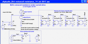
Birt's voicecoil resistance measurement simulation
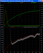
The attached circuit shows the previous thermal model with a 1mA bias current and a filter to see how many stages are needed to get 20Hz ripple low enough and the response time to measure the voice coil resistance. Birt's circuit was designed for operating from 300Hz and did not need a high-order filter. But for use down to 20Hz we need a very high order filter.
With 1mA DC through 8 ohms we have 8mV DC. There is 32uV/degC change and I'd like the filter's remaining ac from 20Hz to be less than +/-5 degC or +/-150uV.
With 80V peak audio the filter rejection in dB is 20*log(0.15mV/80V) or -115dB. But we only have one decade (or two decades) of frequency for -115dB rejection because we want it to settle in around a second.
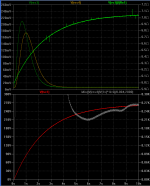
The attached plots show the filter outputs for 30V and 60V drive voltages. I found 4 stages are needed using an fc of 0.5Hz to get the 20Hz ripple below 150uV which as mentioned represents a resistance variation of +/-5 degC.
Notice the large transient of around 200mV. The sinewave starts from 0V. It takes 5 seconds for this transient settles to the 6-10mV range (recall it's 1mV/ohm with a 1mA bias). Then another 5 seconds for the filter to get within 10 degrees of the final true temperature.
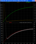
Changing the DC bias to 10mA helps to reach the true reading faster (see 2nd plot). Reducing the filter to 1Hz gives +/-5 degC ripple with 4 filter stages and the transient settles in half the time. Instead of 10 seconds to settle it is now settles in 5 seconds.
There may be a better filter alignment that would settle faster. But even if we use 10mA bias, can a better filter settle in less than 1 second with 20Hz and +/-150uV ac (+/-5 degC)? It seems to a big ask. That's why I was hoping to use the self-heating resistor in series with the speaker to predict the temperature over the first few seconds.
From the previous post (thermal simulation) it needs to have a response time of 100ms to respond to a very high power, eg a (faulty) power amp with 80V DC to the speaker, and I think that is possible since the secondary wire is twisted with the heating wire for quick heating. But I have yet to measure the response time of my 7 ohm secondary prototype (see posts #30-32).
BTW my circuits in post #31 and #32 do not use the Birt method and they are only intended for proof of concept to show how a variable negative resistance can be generated without a multiplier or LDR to cancel the voicecoil resistance increase with temperature.
My compensation approach can be applied to both pure voltage drive and mixed drive, like Idrive and Vdrive at LF. When it is used with Idrive and Vdrive at LF the compensation does not need to be as accurate as with pure voltage drive because it is only around resonance where temperature affects need compensating. I hope to do bench tests soon to see how it all pans out.
...In a following post I use this thermal model with a filter to remove 20Hz leaving the voice coil DC voltage for temperature reading to see how fast (or slow) it settles.
The attached circuit shows the previous thermal model with a 1mA bias current and a filter to see how many stages are needed to get 20Hz ripple low enough and the response time to measure the voice coil resistance. Birt's circuit was designed for operating from 300Hz and did not need a high-order filter. But for use down to 20Hz we need a very high order filter.
With 1mA DC through 8 ohms we have 8mV DC. There is 32uV/degC change and I'd like the filter's remaining ac from 20Hz to be less than +/-5 degC or +/-150uV.
With 80V peak audio the filter rejection in dB is 20*log(0.15mV/80V) or -115dB. But we only have one decade (or two decades) of frequency for -115dB rejection because we want it to settle in around a second.
The attached plots show the filter outputs for 30V and 60V drive voltages. I found 4 stages are needed using an fc of 0.5Hz to get the 20Hz ripple below 150uV which as mentioned represents a resistance variation of +/-5 degC.
Notice the large transient of around 200mV. The sinewave starts from 0V. It takes 5 seconds for this transient settles to the 6-10mV range (recall it's 1mV/ohm with a 1mA bias). Then another 5 seconds for the filter to get within 10 degrees of the final true temperature.
Changing the DC bias to 10mA helps to reach the true reading faster (see 2nd plot). Reducing the filter to 1Hz gives +/-5 degC ripple with 4 filter stages and the transient settles in half the time. Instead of 10 seconds to settle it is now settles in 5 seconds.
There may be a better filter alignment that would settle faster. But even if we use 10mA bias, can a better filter settle in less than 1 second with 20Hz and +/-150uV ac (+/-5 degC)? It seems to a big ask. That's why I was hoping to use the self-heating resistor in series with the speaker to predict the temperature over the first few seconds.
From the previous post (thermal simulation) it needs to have a response time of 100ms to respond to a very high power, eg a (faulty) power amp with 80V DC to the speaker, and I think that is possible since the secondary wire is twisted with the heating wire for quick heating. But I have yet to measure the response time of my 7 ohm secondary prototype (see posts #30-32).
BTW my circuits in post #31 and #32 do not use the Birt method and they are only intended for proof of concept to show how a variable negative resistance can be generated without a multiplier or LDR to cancel the voicecoil resistance increase with temperature.
My compensation approach can be applied to both pure voltage drive and mixed drive, like Idrive and Vdrive at LF. When it is used with Idrive and Vdrive at LF the compensation does not need to be as accurate as with pure voltage drive because it is only around resonance where temperature affects need compensating. I hope to do bench tests soon to see how it all pans out.
Attachments
-
 diyAudio_Birt-voicecoil-resistance-cct_14-Jul-2017.png30 KB · Views: 382
 -
 diyAudio_Birt-voicecoil-resistance-30V-1mA-plot_14-Jul-2017.png20.9 KB · Views: 378
 -
 diyAudio_Birt-voicecoil-resistance-30V-10mA-1Hz-plot_14-Jul-2017.png21.4 KB · Views: 375
 -
diyAudio_Birt-voicecoil-resistance_14-Jul-2017.zip3.7 KB · Views: 40
Removing Birt's massive filter transient
Zero D, Thanks. Do you have a link or anything to share like a Crown circuit?
@All, has anyone tried a better filter?
For the 10mA simulation I tried a Salen/Key 4th order Bessel alignment. With f-3dB at 0.3Hz and for the same ripple as before I got the same transient peak and the same settling time of 2 seconds to within 10 degrees, then it slowly settles to within a few degrees after another 5 seconds. That seems to be the best I can get so far.
The large initial transient (when the 20Hz starts) is a big problem. (I don't think it is something wrong in the simulation). It obviously needs to be blocked out until it has settled to prevent unwanted strange effects and false tripping! But how do we control blocking it?
If we had the rough but fast response of temperature reading from the self-heating resistor then we could use it by differentiation (dTemp/dt) for control to inhibit the Birt filter output until the rate of change falls, then switch to the Birt filter. While the Birt filter is inhibited we can use the self-heating resistor temperature reading. Maybe worth a try.
Improving all the time
Zero D, Thanks. Do you have a link or anything to share like a Crown circuit?
@All, has anyone tried a better filter?
For the 10mA simulation I tried a Salen/Key 4th order Bessel alignment. With f-3dB at 0.3Hz and for the same ripple as before I got the same transient peak and the same settling time of 2 seconds to within 10 degrees, then it slowly settles to within a few degrees after another 5 seconds. That seems to be the best I can get so far.
The large initial transient (when the 20Hz starts) is a big problem. (I don't think it is something wrong in the simulation). It obviously needs to be blocked out until it has settled to prevent unwanted strange effects and false tripping! But how do we control blocking it?
If we had the rough but fast response of temperature reading from the self-heating resistor then we could use it by differentiation (dTemp/dt) for control to inhibit the Birt filter output until the rate of change falls, then switch to the Birt filter. While the Birt filter is inhibited we can use the self-heating resistor temperature reading. Maybe worth a try.
For one, amp output signals are usually BW limited to about 4Hz but your input source is not. Adding a HP filter to the source reduces settling time from 1.78 seconds to 1.44 seconds. The filter responds disproportionately to LF so it helps to remove it if it's not doing anything. A higher order HP filter would probably help as well.
Also, it doesn't make sense to me to apply thermal compression compensation to a current-output amp. If the point of the compensation is to keep voicecoil current constant regardless of voicecoil resistance, then current drive accomplishes this with no help.
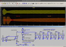
I have altered your jig to a voltage drive setup with HP filter and feedback. The effectiveness of the feedback can be visualized by plotting V(vc1,vc0) and V(in1,In0). When these waveforms track you know that feedback is working.
The feedback gain in this system is 1, so not high enough to oscillate. However the delay of the filter causes some modulation in the compensation.
Also, it doesn't make sense to me to apply thermal compression compensation to a current-output amp. If the point of the compensation is to keep voicecoil current constant regardless of voicecoil resistance, then current drive accomplishes this with no help.
I have altered your jig to a voltage drive setup with HP filter and feedback. The effectiveness of the feedback can be visualized by plotting V(vc1,vc0) and V(in1,In0). When these waveforms track you know that feedback is working.
The feedback gain in this system is 1, so not high enough to oscillate. However the delay of the filter causes some modulation in the compensation.
Attachments
Last edited:
@ Ian H
Crown amplifier circuit diagrams/manuals etc etc, are available Directly from Crown Audio - Professional Power Amplifiers In particular, download & look @ Macro-Tech MA5000VZ schematics
Crown amplifier circuit diagrams/manuals etc etc, are available Directly from Crown Audio - Professional Power Amplifiers
In particular, download & look @ Macro-Tech MA5000VZ schematics Oops in Post #46
Oops. The voicecoil resistance temp. co. was not correct in post #46. Source "B1" needs to include "Re". It was out by a factor of 6.
The attached files are the corrected ones for post #46.
Fortunately it doesn't change the time to reach 150 degC vc limit.
But it does change the power level to the speaker where thermal runaway occurs using current drive; it should have been 100W (not 600W).
This mistake also affects post #47 for the Birt sims. I will update them as a following post.
My apology to all.
To show the response time of the Birt method of measuring the voice coil resistance using a 1mA DC bias I have first made a voice coil model with electrothermal feedback.
Oops
. The voicecoil resistance temp. co. was not correct in post #46. Source "B1" needs to include "Re". It was out by a factor of 6. The attached files are the corrected ones for post #46.
Fortunately it doesn't change the time to reach 150 degC vc limit.
But it does change the power level to the speaker where thermal runaway occurs using current drive; it should have been 100W (not 600W).
This mistake also affects post #47 for the Birt sims. I will update them as a following post.
My apology to all.
Attachments
Oops in post #47
The mistake in post #46 fortunately does not affect the time constants so we get similar outcomes with the mistake fixed.
But the power levels of the sim need to be reduced to stay below thermal runaway; in this case below 100W.
The corrected sims are attached.
There is still the large initial transient when the 20Hz starts and about a 2 second delay to settle to a reasonable temperature reading.
I'm still thinking of a way to suppress this transient. Using a Bessel filter didn't seem to help. Any ideas?
Keantoken's posts #50,51 scales Vin to the power amp (eg a two quadrant multipiler/volume) with V(Res4) to increase the gain in proportion to the real-time vc resistance reading, which works after it has settled -- but the first part of the 20Hz is modulated too much to be usable; illustrating clearly the need to suppress this initial transient error some how.
Oops in post #46...This mistake also affects post #47 for the Birt sims.
The mistake in post #46 fortunately does not affect the time constants so we get similar outcomes with the mistake fixed.
But the power levels of the sim need to be reduced to stay below thermal runaway; in this case below 100W.
The corrected sims are attached.
There is still the large initial transient when the 20Hz starts and about a 2 second delay to settle to a reasonable temperature reading.
I'm still thinking of a way to suppress this transient. Using a Bessel filter didn't seem to help. Any ideas?
Keantoken's posts #50,51 scales Vin to the power amp (eg a two quadrant multipiler/volume) with V(Res4) to increase the gain in proportion to the real-time vc resistance reading, which works after it has settled -- but the first part of the 20Hz is modulated too much to be usable; illustrating clearly the need to suppress this initial transient error some how.
Attachments
-
 diyAudio_Birt-voicecoil-resistance-20V-10mA-cct_20-Jul-2017.png35.8 KB · Views: 412
 -
 diyAudio_Birt-voicecoil-resistance-20V-1mA-1Hz-plot_20-Jul-2017.png30.9 KB · Views: 412
 -
 diyAudio_Birt-voicecoil-resistance-20V-10mA-1Hz5-plot_20-Jul-2017.png29.2 KB · Views: 411
 -
diyAudio_Birt-voicecoil-resistance-corrected_20-Jul-2017.zip93.7 KB · Views: 35
Update
Hi All,
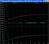
Recap: This thread covers using current drive of loudspeakers at MF+HF and with voltage drive at LF -- current drive at at MF+HF reduces speaker distortions which mainly occur in the MF region while undamped resonance boominess that is the problem with pure current drive. It does not need an equaliser to remove the resonance boominess of pure current drive and is not sensitive to T/S parameter drift with temperature and aging. But there's a problem -- voltage drive at LF brings back volume compression and reduced damping at high power -- two effects which which pure current drive eliminates. So what to do? To overcome volume compression and damping loss at high power we can build compensation for voicecoil resistance change into the power amp feedback path -- this can be done by generating a temperature variable negative resistance to 'eat up' the extra resistance of the voicecoil as it heats up. But to do this compensation we want an accurate estimate of the voicecoil temperature in real time otherwise you get unwanted gain modulation a.k.a. distortion. The Birt method was suggested as a simple way to obtain the voicecoil temperature in real time without any calibration, by forcing 10mA DC through the speaker and use a 1Hz LP filter is used to remove the AC music signal. But with a 20Hz tone-burst we get a massive DC transient and it takes a few second to settle. This is unusable for compensating the voicecoil resistance change in real time. BTW David Birt's compensation worked well on a mid-range speaker (>300Hz), but for a woofer down to 20Hz we get this massive transient a few seconds settling. After trying several ideas none were able to suppress the transient to less than 10 degC, and the shortest settling time was 0.5 second which is still not fast enough for real-time compensation and fast speaker protection.
So what to do? I have returned to my thermal model (Post #30-32) but now with a RC thermal model instead of the self-heating 0.1 ohm resistor.
But a thermal model needs to be set to suit the speaker. Some bench tests are needed to see if we can get away with using typical thermal model values, possibly based on diameter, power rating, etc. Anyone interested? Unfortunately, I am still several months away from any bench tests.
Until tests are done I'll include the Birt method for use with with a steady test tone for calibration.
The extra parts for the Birt measurement and tone generator are minimal; they could be part of a speaker protection PCB. To calibrate a speaker you flip a switch to engage the test tone, wait 10 seconds and read a DMM and adjust a thermal model trimpot to get the same voltage as the Birt temperature. Then return the calibrate switch back to Run and it's done.
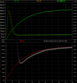
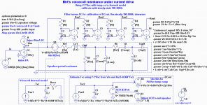
The attached simulation shows the basic circuit in operation with a woofer in a cabinet. The top plots compare the Birt temperature reading with the thermal model reading (these plots are after after calibration). Notice the Birt plot transient (brown) and then several seconds to settle to within 10 degC. This is with a 100Hz sinewave starting at V=0 at t=50ms. Notice also the thermal model reading (pink) has no transient and no settling time delay. Nice.
The lower two plots are the same information as the top plots but scaled in degC (1V/degC). The input voltage to the power amp was chosen as 15V to give a final temperature of 70 degC, which is safe for calibration. The green line at 150 degC the limit for most speakers. BTW T(vc) red plot is under T(vc2) plot, showing the excellent accuracy from the I^2*Rvc estimator after calibration. Nice.
As for the basic circuit (attached):
This temperature estimation method can also be applied to a pure voltage drive power amplifiers -- to remove driver compression, damping loss and crossover misalignment issues. Once this temperature estimation method has been validated by bench tests, a separate thread could be started for those who want to apply it to voltage drive power amplifiers and speaker protection.
...There is still the large initial transient when the 20Hz starts and about a 2 second delay to settle to a reasonable temperature reading.
I'm still thinking of a way to suppress this transient. Using a Bessel filter didn't seem to help. Any ideas?
Hi All,
Recap: This thread covers using current drive of loudspeakers at MF+HF and with voltage drive at LF -- current drive at at MF+HF reduces speaker distortions which mainly occur in the MF region while undamped resonance boominess that is the problem with pure current drive. It does not need an equaliser to remove the resonance boominess of pure current drive and is not sensitive to T/S parameter drift with temperature and aging. But there's a problem -- voltage drive at LF brings back volume compression and reduced damping at high power -- two effects which which pure current drive eliminates. So what to do? To overcome volume compression and damping loss at high power we can build compensation for voicecoil resistance change into the power amp feedback path -- this can be done by generating a temperature variable negative resistance to 'eat up' the extra resistance of the voicecoil as it heats up. But to do this compensation we want an accurate estimate of the voicecoil temperature in real time otherwise you get unwanted gain modulation a.k.a. distortion. The Birt method was suggested as a simple way to obtain the voicecoil temperature in real time without any calibration, by forcing 10mA DC through the speaker and use a 1Hz LP filter is used to remove the AC music signal. But with a 20Hz tone-burst we get a massive DC transient and it takes a few second to settle. This is unusable for compensating the voicecoil resistance change in real time. BTW David Birt's compensation worked well on a mid-range speaker (>300Hz), but for a woofer down to 20Hz we get this massive transient a few seconds settling. After trying several ideas none were able to suppress the transient to less than 10 degC, and the shortest settling time was 0.5 second which is still not fast enough for real-time compensation and fast speaker protection.
So what to do? I have returned to my thermal model (Post #30-32) but now with a RC thermal model instead of the self-heating 0.1 ohm resistor.
But a thermal model needs to be set to suit the speaker. Some bench tests are needed to see if we can get away with using typical thermal model values, possibly based on diameter, power rating, etc. Anyone interested? Unfortunately, I am still several months away from any bench tests.
Until tests are done I'll include the Birt method for use with with a steady test tone for calibration.
The extra parts for the Birt measurement and tone generator are minimal; they could be part of a speaker protection PCB. To calibrate a speaker you flip a switch to engage the test tone, wait 10 seconds and read a DMM and adjust a thermal model trimpot to get the same voltage as the Birt temperature. Then return the calibrate switch back to Run and it's done.
The attached simulation shows the basic circuit in operation with a woofer in a cabinet. The top plots compare the Birt temperature reading with the thermal model reading (these plots are after after calibration). Notice the Birt plot transient (brown) and then several seconds to settle to within 10 degC. This is with a 100Hz sinewave starting at V=0 at t=50ms. Notice also the thermal model reading (pink) has no transient and no settling time delay. Nice
. The lower two plots are the same information as the top plots but scaled in degC (1V/degC). The input voltage to the power amp was chosen as 15V to give a final temperature of 70 degC, which is safe for calibration. The green line at 150 degC the limit for most speakers. BTW T(vc) red plot is under T(vc2) plot, showing the excellent accuracy from the I^2*Rvc estimator after calibration. Nice.
As for the basic circuit (attached):
- The 1st thermal model is for generating the voicecoil dc resistance change with power -- it is not required for a practical circuit when a real speaker is used.
- The 2nd thermal model is for estimating the voicecoil resistance using I^2*Re*(1+0.004*Tvc2) for a compensation circuit (not included here). The 2nd thermal model can use a MOSFET for squaring and another MOSFET for the temp. co. multiply to keep it simple.
- Voltage source V4 is for thermal model calibration -- B4 changes B2's resistance. In a practical circuit B2 is a trimpot for calibration of the thermal models thermal resistance. B2 could be an E2Pot so a micro could do the calibration automatically.
This temperature estimation method can also be applied to a pure voltage drive power amplifiers -- to remove driver compression, damping loss and crossover misalignment issues. Once this temperature estimation method has been validated by bench tests, a separate thread could be started for those who want to apply it to voltage drive power amplifiers and speaker protection.
Attachments
Why compensating for temperature?
I see a lot of discussion about compensating the rise of temperature in the voice coil. I don’t see the problem.
Since May (2017) I have an active current-drive configuration in use. Consisting of:
* 2-way loudspeakers with Scan-Speak drivers and acoustic suspension and without passive filters
* A four channel current-drive amplifier, based on the TDA 7293
* A miniDSP DDRC-24 as pre-amplifier, with Dirac Live and a four channel DAC
It sounds amazing. So I got rid of my Denon amplifier and Acoustic Research speakers.
I use Linkwitz-transformers in the DSP for resonance damping and crossover by shaping the f and Q of the drivers both at the low end and the high end of the driver response. I use acoustic suspension in stead of bass reflex, so the woofers are stable below resonance. The woofers have a fs of 30 Hz, in the enclosure it gives a fb of 60 Hz. The Linkwitz-transformers can change that to a resonance with a f of 30 and a Q of 0.85 (or even lower, the f and Q are adjustable!). The woofer has sufficient displacement (Vd), and music has low power in the lower region, so no problems and distortions here.
Again, I don’t see the problem of raising temperature…
I think the only influence of a rising temperature (as with every rise in impedance) is that the voltage needed for creating the current rises. It has no influence on the sound! If the needed voltage is too high the amplifier starts clipping.
A nice feature of the TDA 9293 that is has a clipping indicator. In the above mentioned configuration I have never seen it clipping. And it can play loud! I have seen it clipping with the Acoustic Research speaker during testing. That was with female voices. I think because of a huge impedance rise at crossover.
Another thing is that voltage-drive has the greatest power demand where the impedance is the lowest and the power in the music the highest (with the 50-50% border around 350 Hz). The greatest power demand with current-drive is where the impedance rises, at the ends of the bandwidth, where the musical power is the lowest. And, around the resonance, where the impedance rises, the demand is even lower than in the middle of the audio range because of the Qms. The higher the Qms the lower the power demand. Also, I selected 4Ω drivers to further lower the power demand.
Then the T/S parameter drift. The result of a parameter drift is a change in resonance frequency and/or Q of the resonance. Both have the effect of a bump or dip in the frequency response. Some comments on this:
* I haven’t seen this. I think the effect is minimal.
* A recompute of the Dirac Live DRC compensates the disturbances, if there is any.
* A more fundamental solution is to recalibrate the Linkwitz-transformers in the DSP by measuring the driver response with close range miking.
So, I would suggest to use current-drive only, also for the low frequencies.
The audibility of thermal modulation (or its absence) frequently appears as a topic for discussion in this forum often without proper qualification, as does the associated subject of voltage vs. current drive.
For the record, unless anyone has evidence to the contrary, we can assume that the thermal time constant in a typical driver is so long as to render thermal modulation of its output inaudible.
The exception to this conclusion arises where we employ a multi-way system and where one band in that system compresses more than another. Here then thermal modulation produces a change in the frequency balance of the complete loudspeaker - normally manifesting itself as a 'softening' of bass notes.
Since there is little low frequency difference in stereo channels, applying a similar argument to stereo loudspeakers, for example, appears unnecessary. In passive loudspeakers, however, we might also postulate an additional change in the crossover alignment.
Also for the record (as I have mentioned in other posts on this forum), I have been using a modified version of Birt's incredibly elegant solution for some time as a means of more than just implementing current drive - albeit always in an active system. In high power applications (i.e. studio monitors and the like), the lack of softening in the bass registers is audible and IMO implementing current drive is worth the effort. However, in all situations including more normal domestic applications (admittedly still active loudspeakers), I can report that the absence of MF colouration due to magnetic non-linearities using current drive has IMO always proved by far the most significant improvement.
Last edited:
I see a lot of discussion about compensating the rise of temperature in the voice coil. I don’t see the problem.
Since May (2017) I have an active current-drive configuration in use. Consisting of:
* 2-way loudspeakers with Scan-Speak drivers and acoustic suspension and without passive filters
* A four channel current-drive amplifier, based on the TDA 7293
* A miniDSP DDRC-24 as pre-amplifier, with Dirac Live and a four channel DAC
It sounds amazing. So I got rid of my Denon amplifier and Acoustic Research speakers.
So, I would suggest to use current-drive only, also for the low frequencies.
Agree on that. I don't see the problem and why we should compensating the rise of temperature in the voice coil. One thing is that is of slow time constant effect. So distortions are not an issue. Slow changes are very well tolerated from psychoacoustic perspective. And compression would be very small for normal music with high crest factor. And compression is for voltage drive which all builds them and don't see problem.
I also drive my dipole bass woofer for many years with current drive only down to 20hz flat and i don't see any problems with compression or similar. They are 12" peerless xxls with very high excursion. and it is for a reason because they are dipole and have to go up and down in centimeters
The only downside is the distortions are higher around resonance compared to voltage drive. But it is only at low frequencies where very high excursions and back EMF does'n provide any negative feedback for linearisation of Kms Cms nonlinearities dominating in current drive at high excursions.My advise would be to use mixed mode amp. With several Omhs impedance at resonance and current drive above. I believe transition from voltage to current with 6dB/oct slope is best. Higher slope could be problematic for box speakers with multiple drivers in same enclosure. Because they interact acoustically a lot and interaction would be signal dependant, those impossible to correct with DSP(at least in easy way). But i am not sure 100% about this at the moment. Just thinking.
Agree on that. I don't see the problem and why we should compensating the rise of temperature in the voice coil.
You may agree on the lack of reasons to compensate for the rise of temperature in the voice coil, but you do that for totally different reasons than I do…
First, with voltage-drive thermal compression has a devastating effect, for several reasons. The time constant for tweeters is around 2 seconds, for woofers it is around 20 seconds. The amount of thermal compression (for voltage-drive!) is between 0 dB (no signal) and 6 dB (on or over the edge of melt-down). And, less sensitive drivers are more sensitive to thermal compression. So, if you have music with soft and louder pieces you loose dynamics. And even worse, the rise of temperature in the voice coil has also a devastating effect on passive crossovers. At -6 dB (the most extreme case) the voice coil resistance is doubled!, so, there is a change of crossover frequency of about one octave (depending on the topology of the filter network). And on top of that the time constant of change in crossover frequency is for tweeters about 2 seconds and for woofers about 20 seconds. So you get peeks and dips in the frequency response depending on whether there a is heating up or cooling down period… And at every moment the amount of thermal compression will not be the same for the different drivers, not for the drivers in the same loudspeaker and not for the drivers in different loudspeakers.
But this all is the case with voltage-drive and passive crossovers. But with current-drive there is no thermal compression whatsoever! The output of a driver depends only on the current (and some driver parameters) and not on voltage, power or voice coil resistance. And if you have active crossovers or passive crossovers designed for current-drive, there is no dependency on the voice coil resistance and thus voice coil temperature.
I don’t see any use of voltage-drive at resonance and of mixed-mode amplifiers. At resonance, with the same excursion (!!) the distortion with current-drive will always be lower than with voltage-drive, because you loose all kinds of current distortion and it introduces no extra distortion. Electro-magnetic damping / back EMF introduces extra non-linearities and phase shifts and is thus not a solution for anything but one of the root causes of the problems of voltage-drive. Use other ways to EQ the resonance peak, and if you do so the distortion will always be lower.
My advise is to stick to current-drive for the whole bandwidth, above, at and below resonance.
- Home
- Amplifiers
- Solid State
- mix current drive with voltage drive at LF?