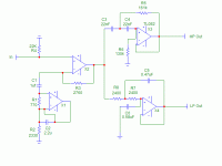
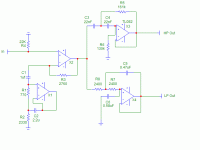
I built this active crossover shown below and posted it in the subwoofer thread. Thought I might check here for the expertise on the noise issue:
I went to the FRD and played with an 80 Hz crossover until I got reasonable parts values. Here's what I came up with. The first two op-amps are the 80Hz boost and the other two are labled for high pass and low pass. I built it using some TL082, as I had some, and with that frequency, I figured they would be ok. I used 15 volt regs (47uF on the input, 0.1 on the output), powered off the amp rails. It seems to work just fine and sounds good with the limited testing I've done. I do get some noise on power down after about 5 seconds, when the main amp caps run out of juice. It's not a dealbreaker, but I would like to eliminate it. Different op amps? I'm using dual 8 pin versions with sockets, so I can easily change.
I'd like to avoid relay's as that would take up too much space and require another power supply. Any other options?
Sheldon
Attachments
rtarbell said:In your schematic in the lower left corner, C2 is shorted out. Is this a typo?
Good catch. Here's the correct schematic:
Attachments
Stocker said:relays can be had smaller than a fingernail, and power can be had by dropping a rail voltage across a high power resistor. Maybe not even that high-power, considering it would only be dissipating for a few seconds?

I'll have to think about this one. Tricky if the relay is only powered during the "noise" event, as this is when supply voltage is dropping to low levels. It's much easier to have the relay short the outputs when it's not powered. An RC delay can be built such that it opens shortly after power up and closes shortly after power down, but before the crossover circuit gags. The output noise doesn't happen until the 35V main supply voltage drops to about 10V. I've done it this way before on a buffered chip amp. Trying to see if some kinkd of SS circuit could be rigged up.
Sheldon
richie00boy said:What is the purpose of your input stage? Why not a standard NI buffer?
Does the noise come out of the tweeter, the woofer, or both?
Not sure what you mean by NI buffer (edit: ah yes, Non Inverted, never mind). In this case the two input op-amps form a boost circuit. With this transient perfect second order filter, the HP and LP are separated (50 and 128Hz for this 80 Hz crossover). A boost with a specific Q is added at 80Hz, such that the combination gives essentially linear phase, like a first order filter. The consequence is that the boost at the crossover frequency has to be eq'd out. But, since the response is linear phase, it remains linear phase after eq. In my case, the eq is done afterware with a DEQX.
Sheldon
edit: This is for the woofer/sub crossover in a four way system. The tweeter/mid crossover and the mid/ woofer-sub crossover is done by the DEQX (three channels). Program found here: http://www.pvconsultants.com/audio/tp/tpdgam.htm
Hi
I'm also anticipating this problem for my pending 3-way active x-over.
My plans include shorting outputs with NC contacts with a multi pole 24vdc relay coil monitoring the opamp supply +/- 12V.
SS design is possible. I have noodled out a prelim design that should work OK, but would have to be simulated and breadboarded. 3 bipolar trans, diode and 6 resistor and electro cap for your 2 output. This could take a few days a still not be audiophile at the end only to save a couple of bucks? I can send it to you with preliminary values if you want to finish the design.
infinia said:Hi
I'm also anticipating this problem for my pending 3-way active x-over.
My plans include shorting outputs with NC contacts with a multi pole 24vdc relay coil monitoring the opamp supply +/- 12V.
SS design is possible. I have noodled out a prelim design that should work OK, but would have to be simulated and breadboarded. 3 bipolar trans, diode and 6 resistor and electro cap for your 2 output. This could take a few days a still not be audiophile at the end only to save a couple of bucks? I can send it to you with preliminary values if you want to finish the design.
Thanks. No hurry though. I'll see how much this bothers me and then decide what, if anything, I'll do about it. I was hoping that perhaps some op-amps would have less of this issue than others. That would be a simple fix. Based on the responses, it doesn't seem so. If I do a relay, I'd just choose a double pole NC. With a simple RC, and powered from the 35V rail, I would have the outputs shunted to ground for a couple of seconds on start-up and a couple of seconds after shut down. All that takes is a little experimentation to get the timing right. I do get a minor thump on start-up too, but it is almost simultaneous with switch on. So the mute relay just needs to react a little slower than the crossover circuit on start-up, and a little faster on shut-down.
Sheldon
Sheldon said:
..... So the mute relay just needs to react a little slower than the crossover circuit on start-up, and a little faster on shut-down.
Sheldon
I'vd just made a relay based mute circuit this way, only I switch off the loudspeakers.
I have not the schematics at hand right now to upload, but the idea is fairly simple.
Start with the transformer output (center tapped) and place a full wave rectifier (one diode on each external lead).
From here make a voltage divider to ground (center tap), feeding the base of a small npn transistor.
At the same time, from the diodes junction (rectified voltage) place a resistor in series with a diode, and an electrolytic cap from this point to ground. This is the DC voltage for the relay.
Now simply connect the relay coil between this point and the transistor's collector.
When powered up, the capacitor will charge with a time constant given by the series resistor and the cap's value.
The transistor base is driven by a grossly clipped full wave rectified waveform, so it will briefly cut off at each mains zero crossing, but will not open the relay, not even buzz.
Now when the mains fails, the transistor will cut within half cycle opening the relay, so we have slow turn on and very fast turn off.
Rmember to place a snubber (diode an series resistor) across the relay coil, not a diode alone since it will slow down opening.
If interested I will post my working schematics.
Rodolfo
Thanks, sounds clever, but probably overkill for my requirements. I don't get the power down noise for about 5 seconds after switch off, so it won't be difficult to just use a simple RC circuit to delay the relay on power up and power down. As long as the delay on power down is less than the 5 seconds, I'll avoid the screech/thump.
Sheldon
Sheldon
Sheldon, don't be shy about using DC blocking caps on active filters outputs. Certainly the resulting HPF from this added part shouldn't interfere with the desired response, or can be even incorporated as part of the infrasonic filter for the bass or LPF side. The resultant zero from the DC block are not likely to change using your custom system. Given your input and output impedances are well known. YMMV
Good point. I'm actually running the outputs of the HP and LP into the regular amp inputs, which has 10uf input caps with about 24k inpedence following the cap, for a pole below 1Hz. I could use a smaller cap, which might reduce the thump but not the squeel. But since you made me think about it, I could resize if I need to for a rumble filter. Because I already have the cap, the problem is not actually too severe, and not speaker threatening So maybe I'm being a bit too anal. Still, what the heck. If I can find a way to easily get soundless on/off, why not?
Sheldon
Sheldon
- Status
- This old topic is closed. If you want to reopen this topic, contact a moderator using the "Report Post" button.
- Home
- Amplifiers
- Solid State
- power off noise

