Hello everybody
I'm trying to build a +/- 15V regulator using TL431 but I feel kind of clueless about the negative regulator. The regulator will be driving a JLH headphone amp(circuit 2 at http://www.tcaas.btinternet.co.uk/jlhphones.htm )
My idea is something like this for the positive supply
and something like this for the negative supply
I only have a trafo that will give +-34V regulated at the moment if your wondering about the high supply voltage.
I'm biasing the tl431 with about 10mA since that should be adequate.
Any thoughts?
Thank you for reading this")
/Lovan
I'm trying to build a +/- 15V regulator using TL431 but I feel kind of clueless about the negative regulator. The regulator will be driving a JLH headphone amp(circuit 2 at http://www.tcaas.btinternet.co.uk/jlhphones.htm )
My idea is something like this for the positive supply
An externally hosted image should be here but it was not working when we last tested it.
and something like this for the negative supply
An externally hosted image should be here but it was not working when we last tested it.
I only have a trafo that will give +-34V regulated at the moment if your wondering about the high supply voltage.
I'm biasing the tl431 with about 10mA since that should be adequate.
Any thoughts?
Thank you for reading this
/Lovan
It might work. One way to find out is to simulate it. You could use the freeware SwitcherCAD (LTSpice) from www.linear.com
The Vbe of the output transistor will be effectively substracted from the 2.5V reference so that negative arrangement is not practical.
You may connect the 5K resistor to the base instead of the emitter and use the TL431 as a plain zener, though. Otherwise, consider a LM337 1.5A negative regulator.
You may connect the 5K resistor to the base instead of the emitter and use the TL431 as a plain zener, though. Otherwise, consider a LM337 1.5A negative regulator.
PA: I have never understood how Spice works but I will try it out sometime.
Eva: Thank you for your reply. If I use a tl431 as a zener how will it compare to a regular zener? better or worse?
Maybe I will just start with zenerregulators for both positive and negative.
I thought that a passregulator would be better than a lm337/317 since I will draw almost constant current?
Eva: Thank you for your reply. If I use a tl431 as a zener how will it compare to a regular zener? better or worse?
Maybe I will just start with zenerregulators for both positive and negative.
I thought that a passregulator would be better than a lm337/317 since I will draw almost constant current?
Eva, you are right here.
You might take a peek at Sonny Andersen's current feedback amp. He uses LM431 for negative voltages.
www.mirand.dk
You might take a peek at Sonny Andersen's current feedback amp. He uses LM431 for negative voltages.
www.mirand.dk
If I remember properly, TL431 is substantially noisier than any zener above 10V (low voltage zeners are noisier too). However, output impedance is much lower for the TL431 thus yielding much better line and load regulation. Also, TL431 has very good frequency response despite its active nature, producing a low impedance ouput up to at least 100Khz.
If your input voltage does not sag too much and your load current is low, you may consider the TL431 as a plain shunt regulator in each rail (see the datashet if you don't understand). That's a simple yet effective solution.
Consider also the LM317/LM337 pair. These regulators are widely available and perform quite well for their low cost.
Draw a schematic. Add a signal generator. Probe the voltages where you are interested. Boom, there you have it. A fast PC is nice to have. My 2 GHz PC has to sweat a bit......Lovan said:PA: I have never understood how Spice works but I will try it out sometime.
Many people here know how to use this particular software so why don't you start to simulate.

PA: I had a quick look at his schematic. It's interesting. I will have to think about how it works for a moment. I'm quite slow I know
Eva: Thank you again. I think that I will try tl431 as zeners to begin with.
I thought about the shunt but I think I would need to use it with a transistor becuase of the current needed.
I will try the LM pairs too. Thank you very much for your inputs.
Eva: Thank you again. I think that I will try tl431 as zeners to begin with.
I thought about the shunt but I think I would need to use it with a transistor becuase of the current needed.
I will try the LM pairs too. Thank you very much for your inputs.
This is proably a better solution for you becuase you don't need the precision from a LM431. With LM317 you'll get a less noisy (probably) PS and you have better cooling and mounting and also more protection.Eva said:Consider also the LM317/LM337 pair. These regulators are widely available and perform quite well for their low cost.
Hi,
All push pull ClassA topologies are not constant current.
This JLH circuit and most ClassA single ended topologies are not constant current.I thought that a passregulator would be better than a lm337/317 since I will draw almost constant current?
All push pull ClassA topologies are not constant current.
How about the LT317/LT337 do they have bettre performance?Consider also the LM317/LM337 pair. These regulators are widely available and perform quite well for their low cost.
They do cost more thow.
Hello, i am a newbie
i try to use tl431(lm431) to make a dual power(pos and neg dc) supply for OP that can replace 78xx 79xx lm317 and lm137 series
due to i think tl431 have better temputure performance than them,and tl431 is cheap
sorry for my english, too bad and too many wrong spell but i believe that you can understand
i don't know how to use tl431 for negtive power , i was confused, infact i design one, but use spice simulate, it can not keep the voltage, with the changes of RL(the load resitense) ,the voltage is change,so that can not fit my needs
then i found fairchild 78xx manual have a tracking voltage regulator schemitic that useing a OP and a PNP to just tracking and follow the Positive voltage,
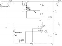
so i use the typical TL431 plus a NPN postive regulator diagram and mix with the tracking way make this one
please see the pic i upload
i try to use tl431(lm431) to make a dual power(pos and neg dc) supply for OP that can replace 78xx 79xx lm317 and lm137 series
due to i think tl431 have better temputure performance than them,and tl431 is cheap
sorry for my english, too bad and too many wrong spell but i believe that you can understand
i don't know how to use tl431 for negtive power , i was confused, infact i design one, but use spice simulate, it can not keep the voltage, with the changes of RL(the load resitense) ,the voltage is change,so that can not fit my needs
then i found fairchild 78xx manual have a tracking voltage regulator schemitic that useing a OP and a PNP to just tracking and follow the Positive voltage,
so i use the typical TL431 plus a NPN postive regulator diagram and mix with the tracking way make this one
please see the pic i upload
Attachments
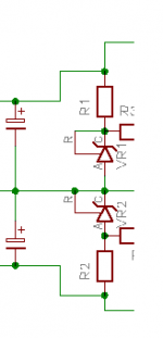
Andrew,
104K/27K=Vz12
It is.The 431 is a shunt regulator and you are using it much like a Zener with feedback. Is this a good way to implement a series voltage regulator?
104K/27K=Vz12
You can do a dual regulator using only positive regulators much easier; simply connect the outputs in series like here
http://www.diyaudio.com/forums/attachment.php?s=&postid=1531867&stamp=1212670865
Have fun, Hannes
http://www.diyaudio.com/forums/attachment.php?s=&postid=1531867&stamp=1212670865
Have fun, Hannes
szcharle said:
then i found fairchild 78xx manual have a tracking voltage regulator schemitic that useing a OP and a PNP to just tracking and follow the Positive voltage,
so i use the typical TL431 plus a NPN postive regulator diagram and mix with the tracking way make this one
please see the pic i upload
Hello, szcharle
I have used same idea in a couple of dual tracking regulators I have built.
I use a discrete 'op-amp'.
Here two BC560C as differential amplifier for mirroring the positive voltage.
My schematic is a very simple version I created just to show idea.
Can be modified for higher gain and more output current, when needed.
Some notes:
- R3 and R6 sets the voltage output for TL431.
- Transistor U1 keeps constant current ~1 mA in TL431 (increased precision)
- The pair U4/U5 is the 'op-amp' that mirrors the positive Voltage
- R7 the 100 Ohm trimmer is for fine adjust the Tracking Negative voltage
- C1 is added for stabilty (avoid oscillation)
Attachments
Attachments
yeah,thanks! Q2 is wrong, in the Fairchild 78xx datasheet, the tracking schemic it is use one PNP, i changed it to NPN(due to i have a lot NPN and few PNP!)
change the Q2 to PNP and swap the Pin 2 and Pin 3 (inverting and non-inverting input of OP LM741) then it works ok!
i found this problem after i made a real PCB and power on
the Neg DC output is about -11.xxV (the input is -12V)
then i came here to check reply and i got you reply
the reason is the NPN, change it to PNP than all ok,
and the OP no need to use a rail-to-rail one, just a cheap 741 is ok!( in fact i suspect if real use a rail-to-rail maybe still got this problem)
and for the spice, i think the spice's simulate OP is too ideal! it ignore the can not rail-to-rail fact, so simulate is success.
thanks again, and I think this circuit is success now?
and i infact not very clearly understand the shunt and the series regulator, but i think 431 is just act as a Zener, and use it as a Zener, and with OP inside it's can feedback,it looks ok?
AndrewT said:q2 is wrong.
104k to 27r cannot be right (9kV output)
The 431 is a shunt regulator and you are using it much like a Zener with feedback. Is this a good way to implement a series voltage regulator?
U3's output is almost at -ve rail potential.
Go and read Jung.
h_a said:You can do a dual regulator using only positive regulators much easier; simply connect the outputs in series like here
http://www.diyaudio.com/forums/attachment.php?s=&postid=1531867&stamp=1212670865
Have fun, Hannes
thanks!
but i think here one problem
the circuit in the link is two positive added together,
but in fact a dual power is estimated that almost no current flow to the ground, the current should from postive to negative,
so i think use two postive added together maybe not the best way,but it's should be a can work way
and i use TL431 due to it's good performance in tempture
i don't know LT1083, i will read it's datasheet,thanks!
- Status
- This old topic is closed. If you want to reopen this topic, contact a moderator using the "Report Post" button.
- Home
- Amplifiers
- Solid State
- TL431 pos & neg regulator