Stuart,
Its good to have you back here!
I am aware of your high power adaption to the 50 but there has to be a very good reason that Dan The Man did what he did in the MK-2 version of the 100.... and I suspect that it has more to do with its ability to drive very low impedances than any other factor. I remember a post about driver current way back in the thread and the lack of ability of the present driver to supply adaquate drive current to the KSA-50 OP stage.
Please compare the older pre 1983 KSA-100 versions with the MK-2 version and let me know what your take is on it and why he went the route he did... perhaps Andrrew would also chime in on this?
Mark
Hi,
it's a while since I last looked at the KSA Klone driver stage, so I'll sumarise from memory.
The MJE1503x pairs will take loads down to 1ohm easily.
2sa649/c669 will take loads down to 2ohm from +-40V rails.
At 1ohm loading they are being stretched to beyond MY limits but only just beyond.
If you want to go to higher voltages then the driver and output stages may (will) need to be beefed up. I would keep the drivers cooler than the outputs if designing for very low loads. CPU cooler with slow fan or copy Still4given's cool inlet over passive sink.
I suggest that if the output stage NEEDS 6pairs then the driver stage probably needs 2 pair to give the current capacity demanded by the multi outputs.
1pair MJE1503x to <5pair 2sa1943/c5200 (2ohm upwards)
2pair MJE 1503x to 6pair 2sa1943/c5200 (1ohm upwards)
1pair 2sb649/c669 to <4pair 2sa1943/c5200 (3ohm upwards)
2pair 2sb649/c669 to 4pair or 6pair 2sa1943/c5200 (1.5ohm upwards)
If you substitute higher power devices than 150W then proportion the number of devices to suit. i.e. 5pair @150W = 3pair @250W
Thanks for your suggestions Mark
Mark:
Yes Im with you, but I have already payed for KSA -50 boards (as you now) and also I have bought components for the KSA-50 (but, I could surely sell those at the Trading Post or in this post)
My first Krell-project will be one of (eg. four of) either the KSA 50 (100W), or the KSA 100 mk-2. I should prefer the KSA-100 mk-2 if there will be boards available.
I have the software needed to make everything for a PCB design including the Gerber generator, drill table, solder masks etc..... (one ore multi layer boards), but I havnt the component needed for to dimensioning the board etc.. and Im not a very skilled designer of Audio-boards.
But I have the experiences for to build Class-A amps (Pass) and thats good. Also I have useful ideas for the design of the driver-output boards. I have ordered Conrads heat sinks for this building project and they will be pre-toled for my output device block (+ OP boards). I could post some drawings of my ideas if need be if this is going to be a new building project.
Mark, what will be the first steps for to design this 100W mk-2 Agreement for a chematics ? or do we already have come to the next stage?
I have design a toroidal custom transformer (at Avel) for this project (for mono-blocks) and it could be used for either the KSA 50 (for 100W) or the KSA 100 mk-2 (76V CT @ 8-9 Amps 6-700VA).
I think your idea for to build this amp was an excellent innovation, especially when thinking of there is not so many building projects for a Class-A amp of 100W+ out there like this one.
Im looking forward to follow this "new" tread. Any more interested out there?
Regards
Mark:
Since you are almost doing the entire KSA-100 MK-2 with the exception of some of the preceeding stages might I suggest that we just do an actual board for the KSA-100 MK-2 including both TO-3 and TO-247 OP boards instead. I'm not sure that the preceeding stages of the KSA-50 can supply enough drive current for 2 pairs of drivers when operating at low impedances. Take a look at the actual schematic of the 100 MK-2 and I think you will agree that Dan went to great lengths to be sure that each preceeding stage was able to make its mark. Also those obsolete VN0210N5 and VPO210N5 devices only operate at about 3 mils so good subs are Zetex ZVP3310 and ZVN3310 and they are readily available and dirt cheap. The 1N5309 current limiter diodes are still made by MicroSemi Corp and in stock at Mouser.
Yes Im with you, but I have already payed for KSA -50 boards (as you now) and also I have bought components for the KSA-50 (but, I could surely sell those at the Trading Post or in this post)
My first Krell-project will be one of (eg. four of) either the KSA 50 (100W), or the KSA 100 mk-2. I should prefer the KSA-100 mk-2 if there will be boards available.
I have the software needed to make everything for a PCB design including the Gerber generator, drill table, solder masks etc..... (one ore multi layer boards), but I havnt the component needed for to dimensioning the board etc.. and Im not a very skilled designer of Audio-boards.
But I have the experiences for to build Class-A amps (Pass) and thats good. Also I have useful ideas for the design of the driver-output boards. I have ordered Conrads heat sinks for this building project and they will be pre-toled for my output device block (+ OP boards). I could post some drawings of my ideas if need be if this is going to be a new building project.
Mark, what will be the first steps for to design this 100W mk-2 Agreement for a chematics ? or do we already have come to the next stage?
I have design a toroidal custom transformer (at Avel) for this project (for mono-blocks) and it could be used for either the KSA 50 (for 100W) or the KSA 100 mk-2 (76V CT @ 8-9 Amps 6-700VA).
I think your idea for to build this amp was an excellent innovation, especially when thinking of there is not so many building projects for a Class-A amp of 100W+ out there like this one.
Im looking forward to follow this "new" tread. Any more interested out there?
Regards
Would there be an advantage if these possibly upcoming ksa-100 MK2 boards were used with the dissipation of the ksa-50?
I have most of the parts for a nice ksa-50, but the ksa-100 mk2 appeals strongly to me.
A lot of parts I have for the ksa-50 can be used for the ksa-100, what I can't use I can always sell.
But I don't want to go for a new case, and the case I have can only dissipate the heat of a ksa-50.
I have most of the parts for a nice ksa-50, but the ksa-100 mk2 appeals strongly to me.
A lot of parts I have for the ksa-50 can be used for the ksa-100, what I can't use I can always sell.
But I don't want to go for a new case, and the case I have can only dissipate the heat of a ksa-50.
Yeah. a new tread for the KSA 100 mk-2, nice
This is perfect.
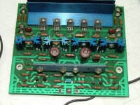
acenovelty:
Yes, it looks very nice, also I liked the mountings of the input stage on same heat sink (same temp on all transistors)
But I would prefer to mount the driver stage on same heat sink as for the output devices (as where the bias device should be mounted)
I would like to post some drawings for my output boards soon so you could se what is my solution for this arrangement.
BTW, I work on the McCAD software from Vamp Inc.
Regards
This is perfect.
acenovelty:
This would be the board to clone?
Yes, it looks very nice, also I liked the mountings of the input stage on same heat sink (same temp on all transistors)
But I would prefer to mount the driver stage on same heat sink as for the output devices (as where the bias device should be mounted)
I would like to post some drawings for my output boards soon so you could se what is my solution for this arrangement.
BTW, I work on the McCAD software from Vamp Inc.
Regards
Pinky, Thanks for creating this new thread!
Everyone,
My original desire was to ultimately build a KSA-80 but the KSA-100 Mk-2 circuit has had me greatly intreguied since the links to Mr. Macleans site was posted. kloning the KSA-80 would also involve aquireing ALOT of even harder to get parts and ALOT of device matching. The KSA-100 MK-2 version will require some matching but not to the extent that a fully balanced amp like the KSA-80 would. On the other hand a PCB design for the KSA-80 board already exists in these threads at DIY!!
Note that there also existed the KMA-100 Monoblock Krell amp that had the addition of regulated supplies for the front end and driver stages, similar to the regulated supplies done in the KSA-80. This additional supply could be a future addition to this amp and one could build a huge stereo amp or Monoblocks. I'd love to see a 6 channel version..... it would probably be the size of a refrigerator.
Al,
I know that at GE he uses Pads which is a very expensive program. I know he also has the full version of Eagle but not sure which release version. The good thing is that he is very up to date on all the industry standard design codes and such and he does alot of high voltage-high current stuff at GE. Allhe does there is PCB design. Anyway I have e-mailed Dave so we'll see if he is interested and has the time.
Getting to the Board.... Itt would be good to make it exactly as the Pinkmouse KSA-50 boards were done, just expanded a bit. Al's boards make bulding the KSA-50 VERY EASY! This would entail expanding the present driver board to accomodate the 2 extra driver devices and expanding the main board to accomodate the current source(?) MOSFETS and extra cascoded(?) predrivers. I would much prefer to see O.P. boards designed for both TO-3 and TO-247 devices done this time around and these should be done as seperate boards completely. Mk21193/94 devices are readily available in both TO-3 and TO-247P packages and are dirt cheap. This will serve to make the whole thing alot more universal and anyone wanting to purchase boards could literally go any route he desired... or could change his mind at a later date as per the O.P. device. So basically it should be the main board and driver board done together and routed to snap apart if desired. Then larger sheets of O.P. boards could be done up to just snap apart into the desired quantuty someone wanted to order. With the KSA-50 some folks didn't want the O.P. boards at all and some wanted extras...... So some board sets had to be sacrificed in order to get the extra O.P. boards. Hopefully they will sell some day.
Andrew,
I believe the rails of the KSA-100 are at +/- 48 to 50 volts. I am also pretty sure that its clip point is around 160 WRMS into 8 ohms... so the 100 watts class A might be valid as the 50 watts was in the KSA-50. Below are links to the schematics of both the main board and the output stage. Let me know why you think the driver and pre driver stages were greatly expanded upon as compared to the Post 1983 version which a link to is also below. There had to be a good reason he went to all the trouble of designing the Mk-2 version other than just plain marketing!! To me the post 1983 version IS nothing more than an expanded KSA-50! It could probably be built on the present KSA-50 board with some minor trace changes.
KSA-100 Mk-2 Main Board
KSA-100 Mk-2 Output Stage
Pre 1983 KSA-100
Every one else please jump in with your ideas and thoughts... perhaps then we can have boards on hand in about 60 days or so.
Thanks!
Mark
The pre 1983 KSA-100 is almost an idental copy of the Aragon amplifiers( Krell has a hand in design) except for the bias that the unit was set at,
The Aragon had an excellent layout, with everything on one PCB that was attached to the hesstsink.............if someone has a picture,it might be a good starting point.
Jam
The Aragon had an excellent layout, with everything on one PCB that was attached to the hesstsink.............if someone has a picture,it might be a good starting point.
Jam
Hi,
looking at the pre83 and Mk2 versions of the KSA100, it appears that they adopted ccs (just like AL) for the LTP and simply added 2pairs of output devices giving a higher voltage version of a KSA50. As someone pointed out a while back this sometimes reduces sound quality.
With the higher driver voltage the driver becomes the limit and this could be what causes returns under warranty and possibly sound quality.
Along comes Mk2 with the return of the Zener fixed LTP source and cascode for the VAS and doubling up the driver ability. But the big change is the intermediate dual complementary LTP FET stage.
The big question:- which of these changes made 100Mk2 better than KSA50 and which made it worse.
Can I suggest that we incorporate ALL the tweeks that Dan had, that make it better, and leave traces in the board for any that cannot be shown to improve sound quality thus making these optional (the PCB space for this will be marginal) and allowing reversion to KSA50 topology where builders can experiment to find the best sound.
Looking back and comparing my driver posting, Dan has 1driver (MJE1503x) to 500W of output devices in the KSA50Mk2 and KSA100Mk2 cf. my limit of: 1driver per 750W of output device and Dan's 100pre83: 1driver per 1000W
The other difference, the driver Re has gone from 25r in KSA50 to 47r in 100pre83 to two times 75r in 100Mk2.
Vbe temp compensation
Hi,
this has been discussed before and I have deliberately NOT looked back at what was posted.
My thoughts are, the output stage is heavily biased and the running temperature depends little on the output power and much more on the ambient temperature. Once up and running and fully warmed up the output stage temperature and the consequent Vbe of the output transistors will vary very little and should not need much in the way of temperature compensation. Even when the Iq varies a little due to ambient changes with the seasons the effect on the total ClassA output will be small and consequently the effect on sound quality will be even smaller.
The driver stage is initially in ClassA and it too will depend on ambient temperature. But, the big differenece here is that the drivers are physically smaller (respond more quickly) and their temperature (Tj) depends much more on the output current. The variation in Vbe of the drivers is likely to be many times higher than the variation of the output stage Vbe (whether it is two times or ten times I cannot analyse nor measure). The Vbe multiplier if closely connected to the drivers Tj can and should compensate for the driver Vbe variation. There is little need to artificially raise the driver Tc to match the output stage heatsink temp and reduce the drivers' ability to cope with it's own loading.
I can see a possible need to optimise the driver Tc and Tj but this could only be done if it were separated from the output heatsink and then driver Re could be used to experiment with optimum level of driver Iq (controlling Tj + Tc).
If KSA100Mk2 is actually a high bias ClassAB design then a small amount of overcompensation in the driver stage will reduce output Iq as power levels rise above the ClassA level. This effect will be quite slow since the output stage has the inertia of eight Tc and a large heatsink to overcome before temperatures start to react. But at least overcompensation at high driver outputs will be in the correct direction if a little output compensation is required.
So my suggestion is that the four drivers and Vbe multiplier be on a common heatsink that strives to keep driver Tc considerably below output Tc.
AndrewT said:Hi,
looking at the pre83 and Mk2 versions of the KSA100, it appears that they adopted ccs (just like AL) for the LTP and simply added 2pairs of output devices giving a higher voltage version of a KSA50. As someone pointed out a while back this sometimes reduces sound quality.
With the higher driver voltage the driver becomes the limit and this could be what causes returns under warranty and possibly sound quality.
Along comes Mk2 with the return of the Zener fixed LTP source and cascode for the VAS and doubling up the driver ability. But the big change is the intermediate dual complementary LTP FET stage.
The big question:- which of these changes made 100Mk2 better than KSA50 and which made it worse.
Can I suggest that we incorporate ALL the tweeks that Dan had, that make it better, and leave traces in the board for any that cannot be shown to improve sound quality thus making these optional (the PCB space for this will be marginal) and allowing reversion to KSA50 topology where builders can experiment to find the best sound.
Looking back and comparing my driver posting, Dan has 1driver (MJE1503x) to 500W of output devices in the KSA50Mk2 and KSA100Mk2 cf. my limit of: 1driver per 750W of output device and Dan's 100pre83: 1driver per 1000W
The other difference, the driver Re has gone from 25r in KSA50 to 47r in 100pre83 to two times 75r in 100Mk2.
the big question...................
Was the ksa100 better than the ksa50?
It had more power so it could drive low impedance speakers (apogee) but what about the sound?
Andrew
i agree with the possibilty of leaving things out.
everyones ears are different.
allan
Hi Mark,
do you have access to Krell specifications?
160W into 8r needs an output of 50v6pk. This is impossible on a dual polarity Vrail= 50Vdc and even less possible if the +-Vrail=48Vdc when fully biased.
A maximum of 120W into 8r is more likely for +-48Vdc and possibly 130W for +-50Vdc. These maximum powers would be at clipping level when distortion is likely to be quite high.
What are the bias settings for the 100pre83 and 100Mk2?
Is there a later (Mk3) release? How do the KMA numbers compare?
I (we) could do with a full set of comparative data before we second guess how the Klone should be designed. It's like selecting the timber to build a bridge but then discover we haven't measured the width of the river.
Awpagan,
a little bit of ingenuity can keep the options open, a bit like Jan's Klone with the VI limiting (use it if you feel the need) or All's piggy back add ons for the very high voltage 50Klone.
Can you tell me, guys, for what do you still can a Krell's ? Personally all Krell's, which I have heard, had audible distortion... Or is main advantage, that they can drive one ohm speaker ? Are you building amp or velding machine ? BTW, one ohm speaker can design only moron....
Hi Upupa,
if your
Sorry, cheap shot you don't deserve. It's the in me that could not desist.
if your
can do this, then I'll buy ten of them.ohm speaker can design only moron
Sorry, cheap shot you don't deserve. It's the
in me that could not desist.Personally all Krell's, which I have heard, had audible distortion...
Actually the open minded view that I've always taken is to say that ALL ampifiers have audible distortion of some sort. The distortion of a giiven amplifier is a certain color and it just depends on what color you like. There is no perfect amplifier
. If we could just get Upupa Epops to contribute to the thread in a positive manner......Andrew,
I agree with your take on the 100's power output. It couldn't be more than 120 watts. I don't have any info on the KMA100... sorry. I doubt that it had any more power output than the stero version which was basically dual mono. I have a picture of the inside of a KMA-100 which I will look for and post later today.
As for the driver and VBE sensor I agree. I just found mounting them on the main sinks alot easier. Also the JAN board had the drvices tabs reversed from each other and the VBE in another position away from the drovers making even mounting to a small common sink a tough job, especially for newbies. Keeping in mind that most of us have fan cooled our amps and mounted the drivers and VBE on the main sink temperature changes and tracking can still occur pretty rapidly but granted not as fast as the smaller tab devices can. Now convection cooling would be another matter and it would happen very slowly!
I am presently re-building my 50 with some of the original heat sink tunnel that Krell used in the production models so my drivers and VBE will be mounted the way you originally pointed out.
Everyone,
As for the PCB if we make up a MK-2 board straight over it would be easily reverse-adaptable to building any of the earlier KSA-100 circuits. Neither myself, Al, or my friend Dave have time to adapt or figure out a universal pcb to accomodate all the versions. I am only willing to foot the bill to have 100 boards made up. Its easy to envision that the Mk-2 board straight over can be very adaptable in itself just by jumpering out certain devices and changing some part values to building the earlier versions of the amp. Hopefully those that are going that route would take the time to share that in a future chart with all of us. However it should be up to each individual building the amp to figure out for him self..... Otherwise this PCB deisgn might go on for two years! So in simple terms the universal board would already exist in the from of the MK-2 board!!
As for parts the only obsolete items are VN0210N5 and VP0210N5 devices. These drvices are only drwaing 3 mils so they an be replaced with Zetex ZVP3310 and ZVN3310 as JWB did in his KMA 160 reverse engineered Krell. HE did not even bother to sink them together since they dissipate so little. So that being said all that need be changed are those devices over to the Zetex unless anyone knows of a better device (I had originally thought of IRF9610 and 610 but the Zetex's spec better). All other parts are readily available off the shelf.
Al,
So that being said how do you feel about doing the Mk-2 board straight over, perhaps adding 2 spots for extra bypass on the main board like you did for the 50 main board. Then just expand on the present KSA-50 driver board? The O.P. boards shouldn't be any big deal and could come last.
Mark
I believe the MKI had 41Vac secondaries, which is 57 Vdc something after the bridge.
The MKI powersupply states 52Vdc at the rails, which should stand for the loaded rail voltage.
160 watts continuous at 1% distortion in 8 Ohms should be in reach of these 52Vdc rails.
The MKII is unlikely to have lower rail voltages than the MKI.
I still have the 1986 test article of the KSA100MKII, the same Loek posted some time ago.
KSA100; 160 in 8 Ohms, 280 in 4, 400 in 2.
The KSA100 was measured to have a soft clipping behavior between 145 and 160 watts in 8 Ohms.
btw: i've heard both the kSA50 and the KSA100 on proper loudspeakers.
The KSA100MKII may have been better on Apogee's, i've never understood the charm of those metal washboards.
- Home
- Amplifiers
- Solid State
- Krell KSA 100mkII Clone