Why? What if he will keep the total bias the same? Even if the total bias current will be twice of original will it put the drivers outside of SOA?
Exactly, these drivers at 60V will deliver 5 amps, even if you halve it for high heat its plenty to reliably drive 4 outputs into high bias class A.
Check the datasheet!..........at 60V will deliver 5 amps............
There's no way that 50W device can handle 300W, not even for 100us.
Check the datasheet!
There's no way that 50W device can handle 300W, not even for 100us.
apologies, I was looking at the outputs datasheet

The driver will handle near an amp at this voltage.
With the outputs having an hfe of 40 at 60v, this driver could push 4 output transistors to 20 amp and only be required to deliver 500mA. To me this is seems quite doable. Is my math right?
Why would you want to double the output transistors for this amp when this amp as designed was able to drive the Apogee Scintilla at 1 ohm loads???
I would think that it would only be required if you wish to increase the supply voltage,but then the whole amp should be somewhat redesigned and optimized.
One of the reasons this amp became legendary in it`s ablity to drive safely 1ohm loads is the fact that it uses two drivers per bank..
I would think that it would only be required if you wish to increase the supply voltage,but then the whole amp should be somewhat redesigned and optimized.
One of the reasons this amp became legendary in it`s ablity to drive safely 1ohm loads is the fact that it uses two drivers per bank..
So is it possible to double transistor amout? Or if I do that should I add more driver transistors? I have JIM's PCB so It seems to be quite easy to just add (double them too) more drivers to backside of PCB to help drivers load?
Hi Jushota,
I think you could, but for what gain?
if you tell forum members what you are trying to achieve you may getter better advice.
SOAR
What is "SOAR?"That's better.
Do a proper temperature derated SOAR into a reactive load for the drivers, just as you should do for the output devices.
Last edited:
Too funny...
See there you go again.... you never call em "Bear" or "Whale" or any such epitaph regardless of the accuracy of such a call...
Now I call her "ex"... The kids and I are much better off now too.
EDIT:
And yes the moderators are MORE than welcome to delete these posts. (wish they could delete the ex too..... )
Last edited:
OK I will save them the effort... will delete all my posts... the idea was to inquire of your welfare... Task accomplished.
No, wasn't for meant for you.. I just figured everyone else didn't want to see our conversation in a Krell thread....
Just a quick post, and a hello !
My amp still works fine and I used it for many many hours.
Still impressed.
Might build another...
Hmmm, "might build another" I like your idea
Finally, I have started to move forward with my own projects.
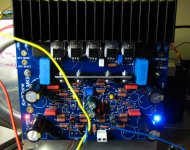
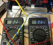
This night I managed to get one main board to work. I just connected the finished board to the DC power source and checked with 2 x Amp meters
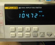
for to have control over current/power drawn. It looked fine in the very first and I checked the DC output. I had to trim the bias pot to max bias for to get some current readings. At the maximum bias set it draw only 83 mA and the total power was calculated to be approx 9 watts. But that was enough for to check everything, also the functions.
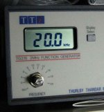
No DC on output, OK. Then I installed a resistor, 4W/1 kΩ paralleled over the output and GND and then I connected a function generator to the input
I checked with a sin wave at the first and everything looked good so far.
At a frequency of approx 170-200 kHz the output swing started to go down but that was Ok if taking to account the feedback capacitor
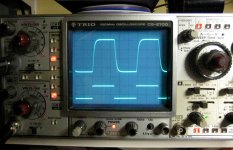
Then I also checked with a square wave and that was really good. I was a little bit curious of how it should behave if driving the amp with a square wave. And there was no surprises to see...
This main board was the first one ever checked and tested so from my point of view it looked promising for the 5 left..... I have a total of 6 main boards
Below are a few pictures of the test set up and of the mainboard under test.
Attachments
PCBs
http://www.diyaudio.com/forums/solid-state/183562-ksa-100-jims-audio-ebay-43.html#post3482136
Check out our thread @Hi all, I know I am very late to try to get started on the ksa100 ( I have been building the ksa50) but are there any P Watts PCB's available? Would prefere bare boards but if populated I would still be interested.
Thanks
Alan
http://www.diyaudio.com/forums/solid-state/183562-ksa-100-jims-audio-ebay-43.html#post3482136
- Home
- Amplifiers
- Solid State
- Krell KSA 100mkII Clone