And (sorry for asking) the Class A max power cannot exceed the Class AB power, ever...correct?
Class AB power is the upper limit?
I guess you could keep biasing up till the Class-A output matches what the rail's limits are, at the point, class A ouput should = AB... theoretically speaking ...
tell us what voltage you want across your 1r0 or 1ohm (reactive) load and we will show you why you should not try to achieve ClassA into a 1ohm load.How would one achieve class -A bias into 1 ohm ?
Since this is the ksa100 Klone thread let's use that as an example.I guess you could keep biasing up till the Class-A output matches what the rail's limits are, at the point, class A ouput should = AB... theoretically speaking ...
Increase the output stage to 12pairs of MJ15003/4.
Increase the bias current to 6A (500mA through each).
The total dissipation is now ~51V * 6A * 2 ~600W
The maximum ClassA output current is ~12Apk
The maximum output voltage is ~45Vpk.
The peak transient current into a an 8r0 resistor ~45/8 ~5.6Apk. This is well inside the ClassA limit.
The peak transient current into an 8ohm speaker is ~45/8*3 ~16A. This is outside the ClassA limit.
If we biassed a 100Klone to about 16A, total dissipation ~1.6kW, it should just about never leave ClassA driving a real 4ohm speaker load.
Biassing a KSA100Klone to 6A can never guarantee that it does not enter ClassAB with a real 8ohm speaker.
Similarly, we hit a current limit long before we hit a voltage limit with low impedance loads, eg. 4ohm and 2ohm.
Last edited:
hi.I have 600 VA torodidal transformer and it has 4x18 volts output.I will connect in series and have 2x36volts ac.I am planning to build a low bias Class AB krell ksa100 or ksa50 version amp with this transformer..How many output transistor should i use? I have MJL1302/3281 and NJW132/3281 transistors.and which of them are more suitable?thank you
tell us what voltage you want across your 1r0 or 1ohm (reactive) load and we will show you why you should not try to achieve ClassA into a 1ohm load.
Yes, i have done the calculations and 1 ohm class A operation is not feasible . I would assume a sliding bias would be the best route , class A for the first 100 watt @ 8 ohm which would net 12.5 watt@ 1 ohm or 25 @ 2 ohm on the revised speaker imp of 1.8 Ohm ...
Now to select the topology to use , any suggestions there ?
KSA 50 value of C105 and C106
I am in the process of building a KSA50 Clone. On the boards I obtained and the circuit diagram the value for C105 and C106 is 22pf, yet on other diagrams I have seen the value is 390pf.
What is the correct value?
I am in the process of building a KSA50 Clone. On the boards I obtained and the circuit diagram the value for C105 and C106 is 22pf, yet on other diagrams I have seen the value is 390pf.
What is the correct value?
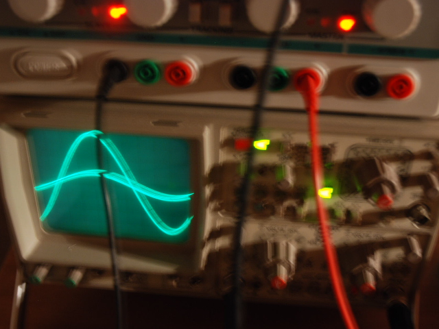
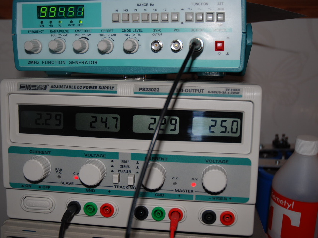
Testing....
Tested for about 1h... will let it be on for another hour tonight...
VCC: 50v - 2.54amp
Emitter: 625mv
Heatsink: ca: 36C with fan at full speed
In/Out signal 1Khz
In: 0.1v / square
Ut: 0.5v / square
Pictures are taken before I went up to 625mv
Question: is the emitter voltage supposed to drop 0.1-0.3v when getting hot ?
If I turn pot up again to 625mv then it after 5min drop 0.1-0.2v..
Guess something isn't stable in my powercube or signalgenerator.
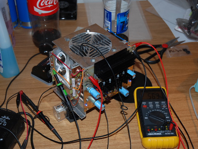
** Just touched my powercube, it's super hot ... hahaha...
Hope it won't burn up...
Question 2:
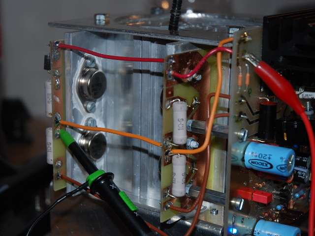
Is it normal that the emitter voltage is NOT the same on all transistors ?
625mv
618mv
630mv
622mv
.....
I am in the process of building a KSA50 Clone. On the boards I obtained and the circuit diagram the value for C105 and C106 is 22pf, yet on other diagrams I have seen the value is 390pf.
What is the correct value?
http://www.diyaudio.com/forums/solid-state/31077-krell-ksa-50-pcb-806.html
")
Hi
I got a question regarding lowering original rails +/-52Vdc - I don't want so much heat
what Is min rails value which I can use with Krell KSA100 mk2 clone pcbs
I will use original bias setting - Ure - 625 mV
I don't want to modify pcb
are rails at +/- 42 Vdc good enough
I got a question regarding lowering original rails +/-52Vdc - I don't want so much heat
what Is min rails value which I can use with Krell KSA100 mk2 clone pcbs
I will use original bias setting - Ure - 625 mV
I don't want to modify pcb
are rails at +/- 42 Vdc good enough
thank you Andrew
great to hear It from expert
resistor values to change are 1 Ohm emitter resistors In output, right
what Is min voltage of rails needed In order not to change the zeners
would you please tell what are your amp specs
I still don't know what toroid to buy - I don't need 100 W at 8 Ohm and so much heat but want to be close to original amp
last question how this amp compares to Nelson Pass amps
I have build F5
I am no expert.great to hear It from expert
I think I am good at sorting the wheat from the chaff, but I get that wrong as well.
 ...............................
hello anyboddy has schematics for power supply on projet krell ksa 100
Here it is
Attachments
- Home
- Amplifiers
- Solid State
- Krell KSA 100mkII Clone