Hi Mark,
what have you done to the heatsink?
It looks like you machined away 70% of it's dissipation capability.
All you needed to do was machine off two fins underneath and the sink would have fitted the extended PCB.
I still don't understand why the PCB needs to be so long. Is it a compatibilty issue?
what have you done to the heatsink?
It looks like you machined away 70% of it's dissipation capability.
All you needed to do was machine off two fins underneath and the sink would have fitted the extended PCB.
I still don't understand why the PCB needs to be so long. Is it a compatibilty issue?
Phew a lot has happenned since I went to sleep last night!
Correct about the feedback loop; I kinda forgot the KSA's are already completed
Regarding the issue of the heatsink shorting out the top layer: the original had the same problem, and it was also fixed by manually drilling removing and drilling out the copper. Otherwise you can always rely on the anodizing of the heatsink
The options are difficult - production houses charge more if you change the holes that they're not through-hole plated since they have to drill them out themself. I can change the pad to a via and thus it will be covered by solder mask, but that will happen on the bottom layer too, and the idea is for the mounting screw to provide a solid connection between the rails and the corresponding collectors. I can minimize the pad size so that it will be easier to scratch off with a sharp knife, but with thick copper on proper boards it will be difficult.
All in all the best solution would be a piece of teflon, silicon or whatever's available.
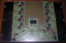
AndrewT: initially the board was much smaller, hence the large open spaces at the sides too (which I stuffed with decoupling caps afterwards). The size increase was to make it a 100% dop-in replacement for both commercial Mk1 and Mk2's.
Not much I can do about the 62pF's position to avoid pushing them down - Personally I prefer a single piece of sheet aluminium for all four predrivers.
I think Mark has shortened the heatsink to make it like the original. Also, it cannot extend much higher than the board or it will touch the chassis cover.
Regarding final changes for the board prior to the group buy:
1) I've shifted VR2, C7 and R36 below the driver transistors.
2) Reversed the bottom side text.
3) Added polarity indicator for the SMD LED's.
4) Increased the mounting holes to 4mm for compatibility with the original's mounting standoffs.
5) Minor changes to silkscreen.
Mark, do you have any plans before heading off to the Group Buy? At least we have to check the necessary heatsink sizes at full power and if possible analysis of the three different FET types. Maybe it's also time to get the wiki up and running in addition to the board orders.
Correct about the feedback loop; I kinda forgot the KSA's are already completed
Regarding the issue of the heatsink shorting out the top layer: the original had the same problem, and it was also fixed by manually drilling removing and drilling out the copper. Otherwise you can always rely on the anodizing of the heatsink
The options are difficult - production houses charge more if you change the holes that they're not through-hole plated since they have to drill them out themself. I can change the pad to a via and thus it will be covered by solder mask, but that will happen on the bottom layer too, and the idea is for the mounting screw to provide a solid connection between the rails and the corresponding collectors. I can minimize the pad size so that it will be easier to scratch off with a sharp knife, but with thick copper on proper boards it will be difficult.
All in all the best solution would be a piece of teflon, silicon or whatever's available.
AndrewT: initially the board was much smaller, hence the large open spaces at the sides too (which I stuffed with decoupling caps afterwards). The size increase was to make it a 100% dop-in replacement for both commercial Mk1 and Mk2's.
Not much I can do about the 62pF's position to avoid pushing them down - Personally I prefer a single piece of sheet aluminium for all four predrivers.
I think Mark has shortened the heatsink to make it like the original. Also, it cannot extend much higher than the board or it will touch the chassis cover.
Regarding final changes for the board prior to the group buy:
1) I've shifted VR2, C7 and R36 below the driver transistors.
2) Reversed the bottom side text.
3) Added polarity indicator for the SMD LED's.
4) Increased the mounting holes to 4mm for compatibility with the original's mounting standoffs.
5) Minor changes to silkscreen.
Mark, do you have any plans before heading off to the Group Buy? At least we have to check the necessary heatsink sizes at full power and if possible analysis of the three different FET types. Maybe it's also time to get the wiki up and running in addition to the board orders.
Hi,
But there is space to the side (end) of the vertically mounted PCB to take a WIDER heatsink. More like the shape of the unaltered sink pic that Mark posted, with just two fins removed from the underside to allow the big sink to fit the PCB.
agreed.it cannot extend much higher than the board or it will touch the chassis cover
But there is space to the side (end) of the vertically mounted PCB to take a WIDER heatsink. More like the shape of the unaltered sink pic that Mark posted, with just two fins removed from the underside to allow the big sink to fit the PCB.
Andrew,
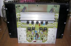
I am attempting to keep it as close to the original as possible. Do a comparison and you'll see that I still have considerably more than Krell did with theirs. Mine is also thicker. The one thing I had to do though was to machine the base of it thinner that I wanted to do. This is because of the short length of the devices leads which limits how far above the board they can actually be mounted. I am about 1/4 of the way done weeding out the old Cerwin Vega amp to test it in. Fortunately the Cerwin Vega amp is modular and has an optput device board that I have easily modified to work with the KSA-100 driver board.
Mark
Attachments
This is obviously way too small a sink to run it in class A without any fan so I am going to bias it into class AB for now... perhaps you all could suggest a bias level for me to set it at to approximately come out in AB mode. The normal class A level is 575 mv across the emitter resistors, K-Amps does have a bias calculator some place though
PWatts...
Am trying to get this going so I don't leave those interested in this hanging for the better of a week as I'm off to a convention in Florida for the moast of next week. We can certainly try the other devices as time goes on but it may be a few weeks before I aquire the parts and get around to actually doing it. On your friends KSA-100 Mk-2 there is supposed to be a network across the output terminals according to the schematic... can you find out the value of those parts for me???
Thanks!
Mark
Attachments
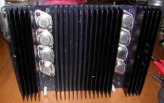
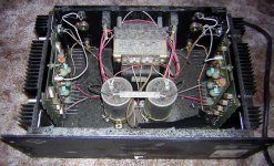
FWIW: The amp I gutted is an old Cerwin Vega A-2200 Sensurround power amp circa about 1974 or 5. It was filthy and was sitting for years. I have completely stripped it down and cleaned it up though and the chassis is actually in pretty good shape. This is strictly meant as a test bed to proove that the boards function properly but I di plan on making it a stereo amp... when I get back from the trip I will assemble the other channel.. When I crank it into Class A I will definately need a 4" fan running at each end of the amp  .
.
Lets get the group buy set up and runnning when I get back from the trip....
BillWW,
Hang in there I'll give you a call when both channels are up and running. LuckyLyndy doesn't seem to interested in this amp for some reason or other.....
Mark
.Lets get the group buy set up and runnning when I get back from the trip....
BillWW,
Hang in there I'll give you a call when both channels are up and running. LuckyLyndy doesn't seem to interested in this amp for some reason or other.....
Mark
Attachments
The Mk2's snubber filter on the output is shrouded inside a plastic cover so I don't have access to the node to measure the resistance, but on the Mk1 it was a 5R6 and 100nF. Progress looking good.
Since everybody is free to experiment with the FET's of their choice, I think we may just then sort out the issue of heatsink sizes before the Group Buy.
Mark, what's the status on the driver heatsink group buy? Separate ones that are nicely anodized will give a so much nicer appearance and I'm sure most wouldn't mind the extra cost. A blue board with blue heatsinks (and blue LED's hehe) will look so cool
Have been listening to one channel of the amp now for several hours. PWatts is right. this is a dynamyte amp! I will almost go so far as saying that one KSA-100 channel is better than a stereo KSA-50!
Bias is set at 300mv across the emitter resistors for now. Runs very hhot but not hot enough to trip the thermal sensors on the amp chassis.
Mark
Bias is set at 300mv across the emitter resistors for now. Runs very hhot but not hot enough to trip the thermal sensors on the amp chassis.
Mark

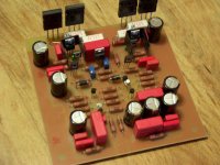
Kudos to Lee1234 to building a Mk1 on such a small single-sides board. Layout's not completely optimal due to that marge MKP caps, but it would make a nice little headphone/tweeter amp. Hope the bias and offset remain stable with the bias transistor separate from the driver/output heatsink.
Mark, I'm continued to be amazed at your speed! Told you the Mk2 sounded good.. personally I wasn't too keen on the Mk1 (in my own system anyway, where I preferred a Rotel).
If I remember correctly Alex said here that Krell Germany has found bias ifor the Mk2 in the region of 380mA to be the optimal point sonic-wise. Perhaps that needs to be investigated so potentially save many builders unnecessary large transformers, caps and heatsinks. The Mk1 I serviced's bias was also reduced from 100W to 80W with no change to the sound, but a noticeable reduction in heatsink temperature and ripple.
The heat tunnels are exactly 100mm high. Must have been made in Europe since all the screws etc. are imperial sizes - a b*tch if you don't have complete sets of imperial sockets, wrenches and allen keys My Mk2 is slowly coming back to life. Had to replace all the trimpots, drivers and output transistors on both channels, and the hookup wire with some fancy van den Hul stuff. Plus van den Hul interconnect wire, rejuvinating the protection and soft-start, SoniCaps on the rectifiers and a SoniCap on the mains at the transformer' primaries.
Mark, I'm continued to be amazed at your speed! Told you the Mk2 sounded good.. personally I wasn't too keen on the Mk1 (in my own system anyway, where I preferred a Rotel).
If I remember correctly Alex said here that Krell Germany has found bias ifor the Mk2 in the region of 380mA to be the optimal point sonic-wise. Perhaps that needs to be investigated so potentially save many builders unnecessary large transformers, caps and heatsinks. The Mk1 I serviced's bias was also reduced from 100W to 80W with no change to the sound, but a noticeable reduction in heatsink temperature and ripple.
The heat tunnels are exactly 100mm high. Must have been made in Europe since all the screws etc. are imperial sizes - a b*tch if you don't have complete sets of imperial sockets, wrenches and allen keys
My Mk2 is slowly coming back to life. Had to replace all the trimpots, drivers and output transistors on both channels, and the hookup wire with some fancy van den Hul stuff. Plus van den Hul interconnect wire, rejuvinating the protection and soft-start, SoniCaps on the rectifiers and a SoniCap on the mains at the transformer' primaries.Well, having that old Cerwin Vega amp really helped me get things done alot faster. The second board is also assembled as well but I have to machine the second sink. Next weekend I should have both channes playing. ONe thing about the 100 that thr 50 is lacking is the ability to shake things in other rooms of my house....amazing LF control and response that just is not there in the 50 .
Mark
.Mark
Congratulations - it beginning to look very good..
Gentlemen
It so nice to see the Krell magic I grew up with beginning to kick in again. It going to be really interesting to see how big this wave is going to get?
With a better board layout- top notch components and better wires I would not be surprised if the new boards outperform the originals.
I wonder how many KSA50 clones will soon be running with the new KSA100 mk2 boards?
Jozua
Krell KSA 100 Mk 2 Spague capacitors
Hi,
I will change the power capacitors in the KSA 100 MK 2.
The Sprague Powerlytic 36DE on the KSA 100 is unavailable !
It´s of 1987.
Sprague Powerlytic 36DE
40000 - 90DC
8747L 4301
Made in USA
+ 95 C
What´s extra or difference to other capacitors ?
Is the Sprague very good ?
What can I to use for a good capacitors ?
Best regards Alex
- Home
- Amplifiers
- Solid State
- Krell KSA 100mkII Clone