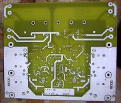
Bottom.... I had just three sets made up. If anyone involved in this project would like to see the full size shots please e-mail me... but you have to be signed up on the board WIKI to buy some in order to receive the shots full size!! I am sending one proto pair to Flodstroem and one pair to PWatts. That way all three of us can build one up and give feedback.
So far the only feedback is that the nemes are reversed... I hope the whole board is not reversed....
Mark
So far the only feedback is that the nemes are reversed... I hope the whole board is not reversed....
Mark
Attachments
Not reversed
I compared the silk screen (last posted picture of it) to the Top side picture and it is right what I can see.
Regards
So far the only feedback is that the nemes are reversed... I hope the whole board is not reversed....
I compared the silk screen (last posted picture of it) to the Top side picture and it is right what I can see.
Regards
Whoops Mark you are correct  - The initial idea was for that part to be on the top layer and I sent it to the bottom at the last minute without reversing it.. the other "All rights reserved" part has been there longer and have been correctly flipped as one can see on the pics. All the rest is correct so no fears.
Since I'm fairly sure there'll have to be some changes made before the group buy anyway it's an easy fix. Besides that everything looks OK-ish as on the Gerbers, and the through-hole plating will make it easy to build despite the Spartan look.
I'll start building mine ASA I get my boards, which should be in around 3 weeks (I guess Mark's will be finished by then)
- The initial idea was for that part to be on the top layer and I sent it to the bottom at the last minute without reversing it.. the other "All rights reserved" part has been there longer and have been correctly flipped as one can see on the pics. All the rest is correct so no fears.Since I'm fairly sure there'll have to be some changes made before the group buy anyway it's an easy fix. Besides that everything looks OK-ish as on the Gerbers, and the through-hole plating will make it easy to build despite the Spartan look.
I'll start building mine ASA I get my boards, which should be in around 3 weeks (I guess Mark's will be finished by then)
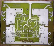
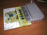
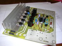
So far so good. A few tihngs simple things I found along the way.
We need to rotate C7 down so it's below the driver heatsink. The way it is now it'll have to be mounted on the back side of the board. Same for the bias pot... We shouldn't have anything above the leads of the driver transistors. I can mill out the heatsink for now though to fit the pot in.
R-37 Silkscreen has been left off. Is right below Q-17.
Can't find J-1 & 2 but J-3, 4 , and 5 are apparent.
Area around C-2,3,4 is pretty tight.
Other than these few things thats about it. Things went together just dandy!
Now on to the Semi's... Hopefully I have enough of them!
Mark
Attachments
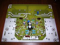
I have two of these heat sinks that I will machine tommrrow morning to fit correctly. I will probably also machine one side of it completely flat as close to the original as I can get it.
Note that I spaced the drivers and bias device up the thickness of two US pennies to account for the heatsink thickness.
Mark
Note that I spaced the drivers and bias device up the thickness of two US pennies to account for the heatsink thickness.
Mark
Attachments
Banned
Joined 2002
Looking good, and progressing fast!
A few notes on Mark's comments:
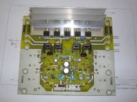
1) R16, R36 and R37 shouldn't have a silkscreen since it's mounted on the bottom. I had to do it due to space issues. R37 can be mounted on the top (so I'll just flip it back up), but I wanted to keep the area clear for people using "foldback"-type heatsinks for the predrivers.
2) J1 and J2 aren't jumpers, they're the input terminals at the bottom. "J" is the reference designator symbol commonly used for all terminals and connectors on PCB's. Since they've got the description next to them on the silkscreen there shouldn't be confusion though.
3) I initally placed C7 and VR2 according to the original Mk2's heatsink, which only started halfway up on the transistors' casings. Because you're going to mount the heatsink on the full case, I'll indeed have to shift them down a bit. Only problem is that it will occupy the clearing I left for the predrivers' heatsinks. Otherwise I can put C7 on the bottom, but it will prevent large exotic caps or otherwise the board will need higher standoffs. Feedback?
4) About the C2,3,4 area... well there's not much to say about it. Any change to it will ripple out to the rest of the board. Same ss with C7, those who want to can put C4 at the bottom. C2 and C3 are the same size as on Al's boards. I also included a blank pad to allow a single bipolar cap at 45degrees angle.
A few notes on Mark's comments:
1) R16, R36 and R37 shouldn't have a silkscreen since it's mounted on the bottom. I had to do it due to space issues. R37 can be mounted on the top (so I'll just flip it back up), but I wanted to keep the area clear for people using "foldback"-type heatsinks for the predrivers.
2) J1 and J2 aren't jumpers, they're the input terminals at the bottom. "J" is the reference designator symbol commonly used for all terminals and connectors on PCB's. Since they've got the description next to them on the silkscreen there shouldn't be confusion though.
3) I initally placed C7 and VR2 according to the original Mk2's heatsink, which only started halfway up on the transistors' casings. Because you're going to mount the heatsink on the full case, I'll indeed have to shift them down a bit. Only problem is that it will occupy the clearing I left for the predrivers' heatsinks. Otherwise I can put C7 on the bottom, but it will prevent large exotic caps or otherwise the board will need higher standoffs. Feedback?
4) About the C2,3,4 area... well there's not much to say about it. Any change to it will ripple out to the rest of the board. Same ss with C7, those who want to can put C4 at the bottom. C2 and C3 are the same size as on Al's boards. I also included a blank pad to allow a single bipolar cap at 45degrees angle.
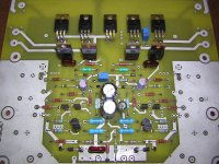
I think you should tell me where you got all them blue resistors. Last time i had some was when my dad gave some to me. He got them from hi end radio/ phone communication equipment..
Remember that I only pay 5 cents a resistor... from the magic surplus store here in SLC.....
Mark
Hi Mark,
that large area of almost empty PCB under the driver collection seems to be an embarassment to fitting your excellent heatsink.
Does the extra empty PCB really need to be there?
What about re-routing the traces and connections at that end to make the drivers/heatsink an easier fit?
What are the blue resistors? They seem a bit bigger than the rest.
film, metal, WW, 500mW, 600mW, 1000mW?
Actually I think the heatsink will for the most part fit just fine if I notch it for the bias pot. C-7 is the only problem and one ond of it could easily be turned down 45 degrees and the one trace re-routed. Back side mounting might be ok but as far as making it interchangable with the original Krell boards I don't kow what will fit in. There is no problem physically with R-37... just missing the silkscreen I.D.
I will post more pics today or tommrrow so you can all see how I intend to mount the sink. I have to do quite a bit of machining to them first.
The blue resistors are just surplus stuff... I think the larger ones are 1/2 watt and the smaller torquoise ones are 1/4 watt.
Mark
I will post more pics today or tommrrow so you can all see how I intend to mount the sink. I have to do quite a bit of machining to them first.
The blue resistors are just surplus stuff... I think the larger ones are 1/2 watt and the smaller torquoise ones are 1/4 watt.
Mark
OK I already modified the board by shifting C7 and VR2 both below the drivers' pins. No modifications will be necessary to the driver heatsink then, but the predrivers will need some ingenuity. However, the predrivers don't need nearly the same size heatsinks as used on the original.
R37 has been placed with the software on the bottom side, so the silkscreen is there - it's just on the bottom where we're not going to use any silkscreen. But I've flipped that to the top as well.
As it is now only one resistor close to the bottom needs to be mounted on the bottom side.
The original's standoffs were long enough to leave quite a bit of room for anything mounted at the back.
As it is now only one resistor close to the bottom needs to be mounted on the bottom side.
Which one is that... I am pretty sure ALL of my resistors are on top... or did I miss one? Or are you talking about there being one below after these mods you just did?
Mark
Mark: There's one crucial resistor at the very bottom going to ground. I don't have the layout or schematic in front of me right now, but I'm fairly sure it's the 825ohm feedback resistor going to ground. You can see its one hole on the ground plane just above the signal input, and the other between the rightmost two blue 150R emitter resistors.
Without it the gain will be very low and quite possibly be unstable too.
Without it the gain will be very low and quite possibly be unstable too.
I also noticed that the order of VR-2 and R-37 are reversed in order fomr the schematic... Probably doesn't matter much though. Also R-36 silkscreen has been left off ... right between Q-11 and Q-12. I found R-16 near the bottom rear just as you mentioned.
All I need to do is attach one sink and then I can fire up the main board which I intend to to without the output stage at first as many of us did with the KSA-50.
Mark
All I need to do is attach one sink and then I can fire up the main board which I intend to to without the output stage at first as many of us did with the KSA-50.
Mark
R36 and R37 were intended to be mounted on the bottom side, hence the absence of the silkscreen and refdes.
Something's not entirely clear from your refdes's - if you're uncertain, check the connections with the schematic instead of the designators.
The resistor between Q11 and Q12 is R37, 7k5.
The other one in series with VR2 is R36, 1k5
The reversal doesn't matter; A+B = B+A.
Firing up the board without the output stage can be dangerous - follow the guidelines as in the Leach assembly guide to complete the feedback loop and disable the bias circuitry, or the amp will probably oscillate.
If you use the original heatsink like Krell used they don't need to be mounted on the bottom. I also found some nifty heatsinks for the pre-drivers, tight fitting and we'll see how they do temperature wise but this is as compact as TO-220 heatsinks get....
Attachments
- Home
- Amplifiers
- Solid State
- Krell KSA 100mkII Clone