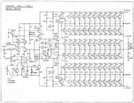
I disagree. There should be a way to drop the bias with that switch to such a low level that the amp will not be generating much if any heat at all. Nelson Pass did this on the Threshold Stasis-1 amp if you take a look at the schematic in the lower left corner. With the Threshold I believe he interrupted a CSS or something to that effect with the Klixoon.
Mark
Mark
Attachments
Nelson Pass did not use a fan, so the cooling capacity did not change as much as on Mark's fan cooled KSA100 when the fan breaks...and the fan will break.
I think the conrol logic is different on a fan cooled amp. If the heatsink temperature goes up enough to trip a coarse sensor, then you have to allow for the fact that the fan could have broken, the cooling capacity has been drastically reduced, and it is best to shut down the amp.
I think the conrol logic is different on a fan cooled amp. If the heatsink temperature goes up enough to trip a coarse sensor, then you have to allow for the fact that the fan could have broken, the cooling capacity has been drastically reduced, and it is best to shut down the amp.
 Sorry to cause this confusion... I forgot to mention that my final version is going to be passively cooled. Will be stripping out my Aleph 2's and will build these as monoblocks. So there will be no fan. The amp you saw inthe photos on this thread is just the prototype to confirm that the boards were ok. I had just wanted to try out any idea that anyone might have had on the proto.
Mark
Can you not just use a parallel resistor switched in and out of the bias network by the thermal switch? <<PinkMouse
I've always been very carefull not to add capacitance or inductance in the Vbe multiplier bias circuit. Prof. Leach also warns about excessive parasitics. This may be an overly conservative position, or amplifier dependent. so please report your results. You may also want to try using the thermal sensor to control a on-PCB local micro relay.
The Leach Vbe multiplier that uses series diodes on the heatsink to reduce RC time constants over the single transistor Vbe multiplier with long wires onto the heatsink has been posted by me. I have one amp that uses this circuit with the new OnSemi ThermalTrack output transistors which include an on-die diode. A stable bias is reached very quickly. Anyone experimenting with a sliding bias(like Krell) amp might want to experiment with these ThermalTrack bipolars.
Mark A. Gulbrandsen said:Thats exactly what I was hoping to do. Lower it to say 50ma standing current.
Mark
I've always been very carefull not to add capacitance or inductance in the Vbe multiplier bias circuit. Prof. Leach also warns about excessive parasitics. This may be an overly conservative position, or amplifier dependent. so please report your results. You may also want to try using the thermal sensor to control a on-PCB local micro relay.
The Leach Vbe multiplier that uses series diodes on the heatsink to reduce RC time constants over the single transistor Vbe multiplier with long wires onto the heatsink has been posted by me. I have one amp that uses this circuit with the new OnSemi ThermalTrack output transistors which include an on-die diode. A stable bias is reached very quickly. Anyone experimenting with a sliding bias(like Krell) amp might want to experiment with these ThermalTrack bipolars.
Hi,
the Vbe multiplier has a parallel capacitor route for the higher frequencies. This HF route will be unaffected by the extra resistor for high bias.
The two lower frequency routes
a) the low bias via the onboard pot+resistor,
b) the high bias via both the onboard components and the extra resistor+thermal switch+connecting wires,
will be relatively unaffected by any capacitance on the longer route.
On the Leach smaller board (Jens') the diodes are remote and without the isolating resistors, it seems to work OK.
An alternative is a resistor+relay set piggy back across the on board components using very short leads, switched remotely by the thermal switch. The longer leads are effectively out of the audio path, just don't have any rough smoothed DC on the remote wires if you think there could be coupling into the low level circuits at the front end.
AndrewT said:
An alternative is a resistor+relay set piggy back across the on board components using very short leads, switched remotely by the thermal switch. The longer leads are effectively out of the audio path, just don't have any rough smoothed DC on the remote wires if you think there could be coupling into the low level circuits at the front end.
Remotely controlled relay sounds nice.
How is the amp affected if the bias is switch while bieg active(used) ??
allan
Hi,
if you want to test the bias change while "on line", I suggest you disconnect the speakers.
There may be a large pulse on the output as the extra resistor goes in or out of circuit.
Obviously, the switch when used in earnest will be "on line" but that should be a one off overheat latch and preferably with an overheat red LED coming on.
AndrewT said:Hi,
if you want to test the bias change while "on line", I suggest you disconnect the speakers.
There may be a large pulse on the output as the extra resistor goes in or out of circuit.
Obviously, the switch when used in earnest will be "on line" but that should be a one off overheat latch and preferably with an overheat red LED coming on.
Thought so, about the spike for the speakers.
So the bias relay should be incorporated with disabling output speakers, activated by either standby and/or thermal and/or dc protection, also switch on?
allan
ps
""How is the amp affected if the bias is switch while bieg"being" active(used) ??""
sometimes i don't spell too good
awpagan said:***How is the amp affected if the bias is switch while bieg active(used) ??
allan
AndrewT said:Hi,
I did not say it will spike.
I said MAY be a large spike.
When you test it you might discover it is benign.
Then you can tell us.
Try asking the KSA50 Klone builders, they had exactly this switchable position on the early PCBs.
Ask me.
I have such a switch on my Krell KSA50; In addition, I have modded the original boards (Jan's) to also have a Green LED to indicate bias setting, though as stated in the KSA50 thread I am embarrassed to say I wired the LED wrong so "green" lights in high bias rather than in the environmentally friendly low bias setting.
Operation of the switch brings in a parallel multiturn resistor that I preset at a reduced bias setting, and if the amp is on I don't get any click or thump or anything like that.
This is benign for me but of course your results may vary.
One thing that I have noticed by changing bias and monitoring the current draw is that it takes a minute or 2 for the amp to arrive at and stay at the new bias setting. (This is easy for me as I have brought out test points from 2 emitter resistors to the back panel for probing; I can measure current draw at any time).
The "sliding bias" of the "newer" KSA50S and KSA100S to me seems a little odd, because if the musical signal triggers a new bias setting, you are not going to hear your amp at that setting for a few minutes.
bringing in the second // pot should increase the bias voltage and increase the bias current.lgreen said:..........Operation of the switch brings in a parallel multiturn resistor that I preset at a reduced bias setting, and if the amp is on I don't get any click or thump or anything like that......
Are you sure you said this the right way round?
AndrewT said:
bringing in the second // pot should increase the bias voltage and increase the bias current.
Are you sure you said this the right way round?
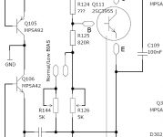
You caught me, I have both resistors in there for regular bias and the switch connects/disconnects the short between the pads (see attached).
So when pads are shorted, you have lower resistance = higher bias. Green LED is on.
When pads are not shorted you have higher resistance = lower bias. Green LED is off.
Confusion is increased due to lack of clarity on the schematic and board. You cannot remove R126 from the circuit so this should really be the "low" bias resistor...but many would read the schematic labels in a manner that implies that R144 is the low bias resistor.
From the wiki-
The bias resistors (R144, R126) are setup such that:
Lower R = Higher Bias/ Higher R = Lower bias.
See [Post ##2527-28]
Attachments
Mark A. Gulbrandsen said:Environmentally Unfriendly / Environmentally Friendly.
Mark
Is this something you would deploy for low volume listening or is it a stand-by feature? Sounds interesting.
Shawn.
Hello all,
While most of us are busy preparing components and finances in anticipation of the PCB's, there is one issue that may be interesting to address if we can find a few volunteers.
It seemed apparant from a dedicated and fine-hearing Krell owner that a lot of seemingly unimportant paramaters can have a noticeable impact on maintaining the "Krell Sound". Some tweaks such as better feedback caps bring improvements but others may, even though on paper being a superior choice, have an adverse effect.
Since most are going to build their amp straight-off there is therefore a chance of the end result being different than it should, which may also have been a cause of the wide variety of comments on the KSA50 clone's sound.
Even though there are a huge amount of variables, the most important ones IMO would be transistor choice and PSU tweaks. If a few of us would volunteer to do a few side-by-side evaluations we can easily put an end to the speculations.
Mark has already found that the choice of FET has made no difference, so feel free to use whatever's the easiest to use. The three families of MJE1503x for the drivers also appear to have little effect besides gain.
What are left are the transistors for the LTP, cascode and output stage.
1) LTP: Comments vary and suitability is possibly influenced by the application as well. On some amps the BC5xx series have been praised, while on others (i.e. Symasm) it was the opposite. Same can be said for the MPS series. The original 2SA970/2SC2240 remains a safe and popular choice.
2) Cascode: the MJE series are the easiest to use but there are alternatives, esp since they don't dissipate significant amounts of power. There must have been a reason why Krell had rather used 2SC2238/2SA968 besides perhaps cost.
3) Output: the concensus seem to be that for longer wires such as the original heat tunnels, the higher-fT transistors may not necessarily be the best choice. Still it would be nice if somebody would build two output stages (e.g. MJ21194/3 & MJ4281/4302) and listen to the difference.
4) PSU: Since the topic of on-board decoupling is still debated, it would be useful if somebody can gradually add capacitance (and the various types provided for e.g. elco and axial MKP) and comment on the changes (if any) in sound quality. Same would go for a small resistor or choke instead of a jumper that connects the driver power from the rest of the board.
Any volunteers? I'll try and do #4 but it would be great if the rest could be subdivided between other builders.
- Home
- Amplifiers
- Solid State
- Krell KSA 100mkII Clone