Hi,
I had originally thought of using the KSA50Ks as active tweeter only drivers.
But after hearing all the tributes began to think they would be wasted on that duty and thought that mid/treble duty through a passive crossover may get best use from the Klones.
However, these recent postings make me wonder if my first instinct is the one to follow.
No conclusion, until I actually try it for real.
Agreed! That is a job for the right tools. I have however cliped out pin by pin other smaller SMD chips knowing well that they had failed and soldered in a new chip... Its not all that hard. When I worked at CANON we repaired the circuitry in the CANON cameras AE-1 and A-1. The A-1 had a large(for the time) SMD microprocessor that I believe was 36 pins.... This was all mounted to a flex board which made it all the more difficult ro remove and replace. This mp was too small to snip all the leads so it had to be unsoldered carefully and the new replacement soldered in. I lasted almost 4 years there before it got to be too much for my eyesbut I still have to see how one can remove a $500 160pin PQFP with it damaging NEITHER the chip nor the board.
 .
.Mark
AndrewT said:Hi,
I had originally thought of using the KSA50Ks as active tweeter only drivers. No conclusion, until I actually try it for real.
How about building a few KMA 100 revII's with a 2-level Class-A bias selector switch on the PCB? This strategy would give a pretty universal amplifier solution from one common design. I think a well designed KMA100 would have better sonics than the KSA50 based upon my past experience on my Apogees. This is why I favor a single PCB KMA100 design suitable for a compact monoblock. I'm interested how the ears on this tread think they compare.
I've become speaker centric over the years..........
I currently combine the active crossover discrete opamps plus two different wattage Class-A power amps onto one PCB and in one chassis. I use the same amp topology, but with a different numbers of outputs and bias. With PASS JFET opamps in front of the power amp, my amplifier input stage performs better with MAT02-MAT03 matched bipolars instead of the matched JFETs that are more commonly used to interface between separate boxed components, power supply grounds, and long cabling.
I thought of this when Mark G mentioned future plans to build a KMA160. I was thinking that stacking the active crossover into the amp chassis and bi-amping might make a hi/lo bias KMA100 design a better system solution than a more complex amp topology like the KMA160 and separate Xover box.
Resistor group buy
Do you like PRP resistors ?
Based on the volume of boards signed up for in the wiki it looks as though we may be able to save $$ even on nice resistors?
An email I received from PRP today, "PRP has a minimum line order of $45.00. We can accept 20 line items at 10 pcs each if each line equals $45.00
Best Regards, Teri"
So it doesn't really work for one for 1-10 qty but if there are 100 or more boards, then this approach would certainly be an option.
Just thought I'd run it by yee all.
Shawn.
Heatsinks Order
Hi
There are two issues that I think we should clarify.
a) Publish a parts list for the project.
b) PCB heatsinks.
Mark are you able to get suitable heatsinks in bulk or must we start looking at alternative options? At this stage this is the biggest concern to me.
If need be I can explore the possibility of machining the heatsinks in South Africa and then supplying to the group?
Jozua
PWatts said:I've posted a full BOM here a few weeks ago but it sort of went by unnoticed by most. I'll do a few updates to it tonight and repost it.
Hi Mark,
Maybe we can start a build wiki and post the BOM there so all can find it. Posts get buried quickly in a popular thread such as this.
Blessings, Terry
If my vote counts for anything, I vote for soldermask.
I am planning on both types to be available. I have not gotten my quote back fomr Advanced as of yet so I will call and holler at them today.
Mark
LineSource,
Do you know where to find a schematic for the KMA100 revII ?
Regards
I think a well designed KMA100 would have better sonics than the KSA50 based upon my past experience on my Apogees. This is why I favor a single PCB KMA100 design suitable for a compact monoblock.
Do you know where to find a schematic for the KMA100 revII ?
Regards
Getting ready for the storm
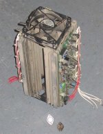
I couldn't turn my back on yet another heat sink tunnel surplus item! This one weighs a ton, has a fan on each end and holds 2x10 TO3's. It is already machined out and the spacing between the TO-3's is generous and the unit is very robust. Each half measures 16.5cm wide by 32.5cm long. This too could easily chill a mean KSA100 down. 
Planning in advance,
Shawn.
I couldn't turn my back on yet another heat sink tunnel surplus item!
This one weighs a ton, has a fan on each end and holds 2x10 TO3's. It is already machined out and the spacing between the TO-3's is generous and the unit is very robust. Each half measures 16.5cm wide by 32.5cm long. This too could easily chill a mean KSA100 down. Planning in advance,
Shawn.
Attachments
Re: LineSource,
I think we can DIY a KMA100 by adding a driver board voltage regulator to this KSA100-II design and putting everything in a good monoblock package.
Flodstroem said:
Do you know where to find a schematic for the KMA100 revII ?
Regards
I think we can DIY a KMA100 by adding a driver board voltage regulator to this KSA100-II design and putting everything in a good monoblock package.
Attachments
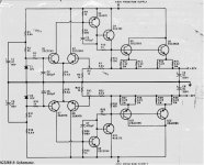
dunno where I found this
Eeeh, on the KMA thread ?

Chok-olate,
any thoughts on why that thing has such a bulky servo ?
Harry3 said:I'm still not clear about the dual driver transistors. What is the advantage?
Do they need to be very well matched so they turn on/ off at the same time?
Also are we certain the cct we have is indeed the last version for the KSA100.
Harry,
The main drawbacks of the antique MJ/MJE devices are the low current amplication factors and low Ft values at high output currents.
At lower output currents their hFe and Ft are pretty good.
One reason why a bunch of the American 80s designs had big arrays of parallel output devices, such as the big Threshold and Rowland Research Model 7 amplifiers. And Krells.
Not just for flashing El Major hardware, for a reason.
At lower output currents, the later Motorola devices reach Ft values of 7 to 8 MHz, with hFe values that are as good as Jappon competitors. See a bunch of posts by one of the Motorola TO3 experts, DJK.
With fewer parallelled output devices the driver section needs to compensate for the lower hFe of the output devices at high output current levels.
As the available driver devices in the 1980s weren't that great at higher load levels either, splitting the load across 2 drivers keeps their hFe value more stable.
The idea of course is that the driver section keeps floating, at the output level where they start switching i doubt that it's a big thing if they don't switch simultaneous.
Dissipation of the drivers gets pretty nasty when the output stage has to drive really low impedance loads, AND doesn't have sufficient high hFe.
As you can see from the schematic the load on the drivers is reduced by halving the bias load, the KSA100 drivers have 75 ohms emitter resistors instead of the 25 on the KSA50.
(40 % more rail voltage, bias current reduced to 1/3d)
A way around the issue is by using more modern output and driver devices, which retain their hFe values up to higher output currents.
Or like in the old days, use a sheetload of TO3s in parallel.
The main reason for using TO3s is because they may be easier to get in some places and/or they are less expensive.
A suggestion might be to match the combined hFe products of driver and output device section.
I was hoping we could chat through another year or so on the different KSA-100 versions.
A thing to be highly aware of is that in low impedance loads the drivers get a serious beating.
If the voltage on the output stage rises, there's more output current going through it, means more current having to flow into the base of the output devices.
Suppose the output voltage doesn't go higher but the load impedance drops. Also means more current, again the base of the output devices need more current.
Then, if the output current becomes so high that the hFe value of the output devices decreases, again there needs to flow more current in their bases.
On top of that, in both cases the voltage drop across the emitter resistors of the output devices goes up because of the higher current going through them.
That means that also the voltage drop across the emitter resistor of the drivers increases !
Means there's also more current going through those resistors when the output stage is driven, NOT less.
And all of that current has to be supplied by the driver(s)
So why were these Krell designs so good in driving low impedance loads ?
One reason => Because they have a very sturdy driver stage compared to the less capable varieties.
In relative terms, the KSA-100 is a good example of an amplifier that can be seen as one with an output stage after the output stage.
The 4 MJE drivers are good for a total Pd of 200 watts, an output stage with a Pd of 200 watts is good enough for an average 50 watts/8 amplifier.
Less robust amplifiers that have to drive a low impedance load can burn their driver section before the output stage blows.
Hi,
Jacco has made the case well for a generous driver stage.
One point I would like to add.
When the output stage is working into a reactive, the driver also feels the effect of that reactive load.
A condition to design for that is fairly extreme (but achieveable) is full output load current when the Vce is =PSU rail voltage.
For the KSA100 into 4ohm this would be about 40Vpk/4r = 10Apk @ Vce=50V giving 500Wpk through those four devices.
The drivers each see half this divided by the output gain @ 2.5Apk (10/4).
The driver dissipation is about 49V*5/40~=6Wpk.
A single driver would be dissipating 12W for the same 4ohm load.
The numbers for 2ohm (and god help us, 1ohm) get much worse.
Hi Tom,
that tunnel leaks.
It will work much better if you can "tunnel" it.
I note that the two sinks are spaced quite far apart and the fins on the outside are in passive air.
Can I suggest you make a sheet metal tunnel and bolt both sinks inside it but much closer together. A small gap between the outside fins and the tunnel inner wall will work quite well.
Remove the fan that is sucking and place the pushing fan at the bottom.
Now you might get 5pairs up and running (but how do 5pairs fit on twin drivers?).
- Home
- Amplifiers
- Solid State
- Krell KSA 100mkII Clone