Any other suggestions/comments?
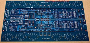
The only thing that comes to mind is that it would be easy to move the pre-drivers slightly up and far enough apart to accomodate the standard small fined heatsinks as Floedstroem mentioned and as Krell had used on their amps. Just move them up and apart into the green area a bit to apace them further apart to give room. that should be pretty easy and not require any re-routing... just repositioning.
I have thought it out and I agree that this board should stay one piece and that it also needs to be a drop in replacement for the KSA-Mk-1 version... screw holes and size from the original KSA board are paramount to take into the new board design. Since I will be supplying the heatsink with the boards this shouldn't even be an issue... and the heatsink we will be using has much more dissipation area than the original one Krell used.
Also If I make the run of boards they will be 2 oz copper same as the KSA-50 boards were... and gold plated for sure. This will aid in pads not comming loose from too much heat and it will also serve to sink the heat better for the Zetex devices. The boards also need to be a close color to the original Krell board so owners of the amps can do a board change with very little astetic change.
Linesource,
This board has to accomodate everyone within reason. Some may use flat back sinks and I for one will be using the exact same air tunnel that Krell used since I have 2-four foot sections of it. Others might use the big square heatsinks such as were used in the KSA-80. All in all a one piece board is not practical. What might be practical would be to make several seperate output boards for several different devices. I use TO-3's but many others use the TO-247 package. Your input on designing seperate output boards might be helpful though. I agree on making it a monoblock.... its way too heavy otherwise. I have a 2 kva tranny just in my KSA-50!
Mark
I agree to Marks comment:
That picture of the small TO-220 heat sink I have posted earlier in the thread had the dimension w=34.5 D=12.5 and H=38 (all in mm). I have made a footprint for this sink including mounting holes(either solder or screw holes) and for the TO-220 footprint. If placing those sinks in a straight row this types will need a board which is 145 mm wide. I think this is a standard dimension for this type of TO-220 extruded heat sink (AAVID). Forgot what dimension your board was.
PWatts:
If its any help I can send/e-mail you this footprint so you can check this out (but Im not sure about the file-format I and you use in the CAD softwares).
Regards
The only thing that comes to mind is that it would be easy to move the pre-drivers slightly up and far enough apart to accomodate the standard small fined heatsinks as Floedstroem mentioned and as Krell had used on their amps. Just move them up and apart into the green area a bit to apace them further apart to give room. that should be pretty easy and not require any re-routing... just repositioning.
That picture of the small TO-220 heat sink I have posted earlier in the thread had the dimension w=34.5 D=12.5 and H=38 (all in mm). I have made a footprint for this sink including mounting holes(either solder or screw holes) and for the TO-220 footprint. If placing those sinks in a straight row this types will need a board which is 145 mm wide. I think this is a standard dimension for this type of TO-220 extruded heat sink (AAVID). Forgot what dimension your board was.
PWatts:
If its any help I can send/e-mail you this footprint so you can check this out (but Im not sure about the file-format I and you use in the CAD softwares).
Regards
I could check the board but, the file format...hmmmm..
PWatts:
I can import file format no other than the Router ASCII documents. If its possible with your CAD-program to convert document (eg. "export file as ...........") to this format I can do the check of whole board. It won´t take a long time for me to do the check.
Regards
PWatts:
Somebody would also need to double-check the board for faults. Preferably someone who has P-CAD 2004
I can import file format no other than the Router ASCII documents. If its possible with your CAD-program to convert document (eg. "export file as ...........") to this format I can do the check of whole board. It won´t take a long time for me to do the check.
Regards
Hi Mark,Mark A. Gulbrandsen said:
I for one will be using the exact same air tunnel that Krell used since I have 2-four foot sections of it.
Mark
After owning KSA100 and KMA100s I would never own another amplifier with a fan. NEVER! I could alway hear the Krell fans, the fan sucked in a lot of dust that required frequent cleaning, and all of the fans broke after a few years. None of Krell's current products use a fan - for good reasons. I cannot think of a top ranked amp that uses a fan.
A high power Class-A amp that relies on natural convection air cooling needs 2.5"-3" deep fins, separated by 0.1"-0.2", lifted about 1"-2" off the floor to create a thermal pump to flow enough air mass to transfer and conduct the heat.
I would ask all builders to re-consider the single PCB design using natural convection air heatsinks like the KL-271 profile. One team engineered complete reference design would give high novice success and still allow experts to make modifications. It sounds like very few builders plan to use this PCB to replace old Krell PCBs, as these should be repairable.
Attachments
Linesource,
There already exists a board you can get from China if anyone wants to build it that way. So why waste time designing one when one already exists.
The KSA-50 board as it was done by Pinkmouse with input from the group has worked out extremely well and all that have been built so far have been VERY sucessful.
I'm not a big fan of plastic power devices and thats my main reason for using the original tunnel design sink. And ok, I got the 4 foot sections as surplus very cheap. Flat back sinks are very expensive to buy new and are not easily adaptable to the TO-3 without another adaptor to connect the TO-3 to the sink.... adding another thermal resistive joint and decreasing transfer efficiency.
Although I will P to P wire my O.P. stage I can see merely taking the Pinkmouse output board and expanding the number of devices on them to the number agreed on. Then making them available with this board or as two snap off boards connected to the main board. The latter was done for the KSA50. This still makes wiring the OP stage a snap and with a very minimum of short run hard wiring involved.... The main thing is that going this route keeps things much more flexible and the group order will be larger and boards will cost less.
IMHO Krell did very little in regard to fan type or optimum operating speed/vs. Noise level. I won't argue on fan reliability though... its always a problem. Because I carefully selected my fans I can't hear them on my KSA-50. I coulda made yours virtually silent and with an fan life of about 5 years if it were left on continously.
The end result of this project has to be aimed at the many, not just the few. The sinks you mention are not easily or economically available in all the countries this amp might be built in. This project has just really gotten underway and the addition of output boards is cetainly very doable.
I don't think you will find many novices building this amp irregardless of how the board is done since the cost is going to be quite high because of power supply and heat sink requirements.
As for owners upgrading their amps that is totally unpredictable but making a board that will retrofit in at this point in time is a cinch with the present design. This covers yet another possibility. I for one would certainly be willing to make assembled and tested boards available to owners and service shops to do the upgrade. In fact the Pinkmouse KSA-50 board would easily retrofit into an old KSA-50 if the driver board were left attached to the main board.
Mark
Attached image of "a" China KSA 100 PCB.
I owned both KSA100 and KMA 100, and the KMA100 was significantly superior, stronger bass, sweeter high frequency ...not sure why ...could be regulated power supply for front end driver stages ....which would also fit on single large PCB. Anyone else own both and can comment?
I owned both KSA100 and KMA 100, and the KMA100 was significantly superior, stronger bass, sweeter high frequency ...not sure why ...could be regulated power supply for front end driver stages ....which would also fit on single large PCB. Anyone else own both and can comment?
Attachments
From Krell Website....major product introductions
1980
Dan and Rondi founded Krell in order to bring new amplifier designs to market unfettered by the understandings of other engineers and executives about product viability and design.
Krell introduces its first product, the KSA-100, which is the first high-power, high-current, true Class A biased stereo power amplifier to enter the market. The young company struggles to meet unexpectedly high demand as the KSA-100 is embraced by audiophiles of the time.
1982
Krell introduces the KSA-50, a smaller and less-costly version of the KSA-100. Again demand soars beyond Krell’s ability to supply.
1983
KMA-100 and KMA-200 mono amplifiers introduce DC coupling from input to output, eliminating capacitors from the signal path. They also contain fully regulated power supplies for the front-end voltage gain stages and sophisticated protection circuitry for the output amplifiers. These innovations, coupled with massive power supplies, enable Krell amplifiers to drive any speakers with ease.
1987
The KRS-200 mono power amplifier brings convection cooling to Krell products, eliminating the previous fan cooling. It doubles the standard for Class A power and quickly becomes the reference standard for modern amplifier design. It also sets the world standard for substance, 5.6 cubic feet and 240lbs!
1988
With the KSA-80 and KSA-200 amplifiers, Krell introduced fully balanced amplifier design, which maintains balanced operation from input to output.
1989
Krell pioneers the use of 64X oversampling in digital circuitry in the SBP 64X digital to analog converter.
Far as I know the KMA-100 regulated supplies were similar as was done for the KSA-80. That power supply schematic is on page 5 of this document in the lower left corner
Mark
Mark
It's great to hear people are agreeing with the idea of making it a drop-in replacement for existing KSA's - I know somebody who owns both a MK1 and a MK2 and I'm sure he'd like the oppportunity to upgrade the Mk1 without risk of damaging the boards. Same goes to boost the Mk2 with better quality components without having to rape the old boards.
Regarding the position of the predrivers: They cannot go higher or lower, i.e. vertical axis is fixed. Lower and it goes into the already occupied space, and higher it will limit the area for the driver heatsink even more. I can shift the outer ones a bit more to the sides though, but it will lengthen the signal path.. guess I'm overly cautious since I'm still in the mindset of doing gigabit digital designs
One has to keep in mind that the inner two predrivers will dissipate less than 100mW each and is likely to be fine with a small clip-on heatsink or even no heatsink at all. The outer ones are about 1W each.
I thought more in the line of a single piece of angle iron for the lot instead of separate heatsinks, one per pair. That looks so much better than the four singles in the original which IMO looks quite dodgy. But if the voice of the masses says same sinks, so be it. Flodstroem, please email me the footprint, I'll msg you my address.
145mm wide board is no problem (I think the original is 150mm), but to space the predrivers so far apart is going to mess with the design. Isn't it possible to use narrower sinks or something? Or smaller ones for the lower-power ones? Has anybody ever felt how warm these things get on the original? I know the drivers get way too hot to my liking but cannot remember the predrivers.
Alex, if you see this, would you please do the effort of drawing up an exact picture/description of the original board wrt dimensons and positions of the wire pads and mounting holes?
Linesource: The first time I read the part of Krell introducing the SBP I thought for a while it stood for Sound Blaster Pro
Hi Line,
Can you add the Mk2 dates into your time line?
I had not realised that Krell are the young whipper snappers of the industry. Just goes to show how quickly they built up their reputation.
Pwatts,
the LTP face to face can be achieved for both cbe pins and for ecb pins but not for the reversed ebc pins of the MPSA types (but nobody with any sense will use these low gain low fT devices).
layout the pin holes as follows:-
ecbe
ebce
connect the respective e to e in the gap between the facing transistors.
Only one trace from the remote side collector (for the right hand pair) needs to be on the top side to lay directly into your PCB layout.
the base can be set back to form the traingular layout often found in To92(x).
what size was/is it?KRS-200 mono power amplifier .....5.6 cubic feet
Can you add the Mk2 dates into your time line?
I had not realised that Krell are the young whipper snappers of the industry. Just goes to show how quickly they built up their reputation.
Pwatts,
the LTP face to face can be achieved for both cbe pins and for ecb pins but not for the reversed ebc pins of the MPSA types (but nobody with any sense will use these low gain low fT devices).
layout the pin holes as follows:-
ecbe
ebce
connect the respective e to e in the gap between the facing transistors.
Only one trace from the remote side collector (for the right hand pair) needs to be on the top side to lay directly into your PCB layout.
the base can be set back to form the traingular layout often found in To92(x).
Hi Pwatts,
can you arrange a little space around each electrolytic so that larger footprint types can be substituted (either because a builder has them available or as a larger value modification)
Could the DC blocking caps (the back to back pair) have pin locations added for 2 series inverse parallel protection diodes (4 required for 1.4Vmax) and a pair of 0.1inch pitch pin locations for a shorting plug for easy DC coupling experiments.
What about space for a second Iq adjust pot for lower standby dissipation (or summer use)? and again a pair of 0.1inch pins to connect to a remote relay or heatsink switch.
And some holes for attaching test probes to loops or single pins.
Good idea AndrewT:
Yes this is a good idea to make holes for test pins Very beneficial idea (remember days when all went wrong: trying to fit "big" test pins on small transistor legs when doing repair work ending with MORE repair work, sometimes also with that famous "phshhhh-----poff" and there came the smoke
 )
)
I will leave it to you for to decide location and number.
Regards
And some holes for attaching test probes to loops or single pins.
Yes this is a good idea to make holes for test pins Very beneficial idea (remember days when all went wrong: trying to fit "big" test pins on small transistor legs when doing repair work ending with MORE repair work, sometimes also with that famous "phshhhh-----poff" and there came the smoke
)I will leave it to you for to decide location and number.
Regards
LineSource said:sets the world standard for substance, 5.6 cubic feet and 240lbs!
Add the price to your list ($30K in 1990 overhere, 22,5K for the KRS-100)
No SS amps that were more expensive, only a couple VTs.
KSA-80B/KMA-160: 23" x 9" x 21"
KSA-200B/KMA-400 : 23" x 9" x 28"
Theoretically bridging should give a 4x increase into the same load (ignoring losses
Bridged amplifiers have power figures based on 4 Ohms output with regard to distortion.
A lower load impedance leads to higher distortion, a general characteristic.
Theoretically it is twice the 4 Ohms continuous output at the same distortion level.
The most important downside of bridging amplifiers(imo)
Hi Pwatts,
could be melf (smd) diodes on the back and use no extra board space.Could the DC blocking caps (the back to back pair) have pin locations added for 2 series inverse parallel protection diodes (4 required for 1.4Vmax)
Hi AndrewT,
I'll see what I can do about the diodes and capacitor size. I used the same size electrolytic as on the PinkMouse boards, and for people using 6.3, 10 or even 16V it should be big enough though. The SMD diodes may be a problem and will probably look a bit tacky for those using them, but I doubt if it will be a popular mod. The shorting jumper may be a good idea though.
The low-bias switch option was added to the Delta Audio boards, and nobody I knew actually used it. Is there anybody here who SERIOUSLY think of using it? Since there is some space at the side of the board I can perhaps even include footprints for a few popular relay sizes, but please don't overcomplicate things if nobody's going to use them.
Regarding probe hooks: I use them in all my designs, but why bother with this one since all the components are leaded? Just lift the legs slightly up when soldering the resistors and there you have your hook free of charge. However, name the nodes you want hooks and I'll see if I can fit them in. One hook I always use is a nice big fat hole for a proper ground pin for the scope ground. I've had enough smoke from a crocodile clip escaping from a dodgy connection and shorting out something to ground that shouldn't be
I'll try to see what I can do about the transistor facing. At the moment it's configured for the cbe transistors such as BC546/556 which IMO are good, simple and easily available.
KSA 100 Mk2 Boards
Pierre
The concept boards looks excellent and the speed this project seems to be developing is most impressive.
I am pretty certain that everyone agrees that this project must be considered as a no-holds-barred attempt at improving upon the original KSA100 mk2 sound quality whilst retaining the longlivity of the orginal amps.
Jozua
Looking a little bit further
Does anybody thought of a proper power transformer for this amp? Are you going to use the common mains transformers sold by Farnell/RS Component/Mouser/ Digi-Key/ or what ever or have you consider a custom design?
Why Im picking up this question now is because the long lead-time for a custom production (maybe 4-8 weeks after order is placed).
I will consider a group buy for this part as same as for the other parts. I have a Contact at the Avel Lindberg (first company to supply Krell with transformers).
If there is someone else who have a contact or know a cheap supplier for a mains transformer GB, you may step in here.
Specification for a main transformer would be same as Krell´s (main criteria was: DEAD SILENT @ full load = , Potted in a can for aesthetic purpose and enough power to the amp= high efficiency)
In March this year I got a quotation for a such a transformer from Avel (ca £ 100.00 net each for a one: 2 x 38, + 2 x 45V 600VA minimum, including a relay drive voltage of 12V @ 1.2Amps if ordering a min. of 10 pcs) This type meant for use in mono-blocks, not for a stereo amp)
I know more regarding this issue in next week......................
Any comments would be appreciated
Regards
Does anybody thought of a proper power transformer for this amp? Are you going to use the common mains transformers sold by Farnell/RS Component/Mouser/ Digi-Key/ or what ever or have you consider a custom design?
Why Im picking up this question now is because the long lead-time for a custom production (maybe 4-8 weeks after order is placed).
I will consider a group buy for this part as same as for the other parts. I have a Contact at the Avel Lindberg (first company to supply Krell with transformers).
If there is someone else who have a contact or know a cheap supplier for a mains transformer GB, you may step in here.
Specification for a main transformer would be same as Krell´s (main criteria was: DEAD SILENT @ full load =
, Potted in a can for aesthetic purpose and enough power to the amp= high efficiency)In March this year I got a quotation for a such a transformer from Avel (ca £ 100.00 net each for a one: 2 x 38, + 2 x 45V 600VA minimum, including a relay drive voltage of 12V @ 1.2Amps if ordering a min. of 10 pcs) This type meant for use in mono-blocks, not for a stereo amp)
I know more regarding this issue in next week......................
Any comments would be appreciated
Regards
Hi,
if the KSA50 had a pair of 400VA, I cannot see the KSA100 having less than 750VA.
I suspect it would perform better with at least 1kVA and close to 3% regulation.
A gauss band and electrostatic screen might elevate this custom job above the regular off the shelf items.
if the KSA50 had a pair of 400VA, I cannot see the KSA100 having less than 750VA.
I suspect it would perform better with at least 1kVA and close to 3% regulation.
A gauss band and electrostatic screen might elevate this custom job above the regular off the shelf items.
- Home
- Amplifiers
- Solid State
- Krell KSA 100mkII Clone