 )
)The heatsinks would be a welcome bonus, but I'm concerned about cost - not only the materials, but also the shipping for overseas builders since a padded envelope is unlikely to be feasible.
Shipping overseas is a flat 9.95 to all but a few locations. Italy is one exception as they require a special padded envelope that costs a few dollars more. I can't see any extreme shipping expense doing this....
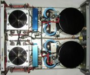
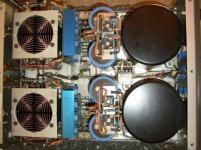
The KMA-100 regulators are located on a seperate board. The KSA-80 regulators are on each channels audio board... and those are quite large boards at that! The driver boards are seperate and very small and pluggable between the main boards and output stage to make re-configuration to a KMA-160 very easy.
You better think GB for those Zetex MOSFETs.
None of the Zetex devices we'd be using are hard or expensive to obtain... less than $2.00 each in single quantity. Digi-Key has a huge Zetex inventory.
Zetex:
ZVN/ZVP 2110G is <$ 1.00 if buying minimum 100pcs from Mouser Electronics, also I have found the Philips/NXP´s (Vertical D-MOSFETs): BSP122 (N-ch) and BSP220 (P-ch) could match those Zetex which means we have more than one alternativ (they also came in SOT-223 pack)
The Philips BSP series is also a rather cheap part (<$ 1.00)
Regards
ZVN/ZVP 2110G is <$ 1.00 if buying minimum 100pcs
$60 for 100 overhere.
AndrewT,
Zetex is 59-75pF maximum Ciss (N-ch), Supertex is 85pf Ciss typical (N-ch)
and Zetex P-ch is 100pF Ciss maximum, Supertex is 90pF typical (P-ch), a rater close match I think. All the other (TO-220 typ) IRF, IRFD and similar has a Ciss of several hundreds of pF.
Also the linearity could be a question for the types that has a higher G-treshold other than those three brands mention in here (Zetex, Philips and Supertex is same, 0,8-3,5V max), other has a 4V G-tresh.
Zetex, Supertex and the Philips/NXP (BSP-series) are all Vertical D-MOSFETs if this counts.
It is hard to find a closer match other than those types, especially if body-size/packaging is an issue (you dont want to solder a SOT-23 when you could use the SOT-223 or the TO-92 packaging)
I think the Zetex could be a little bit faster than the Supertex (originals) due to the lower input gate capacitance ("Ciss") than the Supertex, but this is only a qualified guessing?
Regards
Zen Mod,
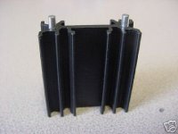
Yes I agree, better heat transfer to outer part of the sink. Also an easy mounting to the board
Regards
No.2 is best ;
fattest core - better heat transfer
Yes I agree, better heat transfer to outer part of the sink. Also an easy mounting to the board
Regards
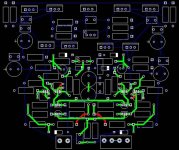
OK, I'm a man of action, so here's the preliminary layout. The board is shown from the top, with the green being the bottom routing and red the top routing. The top part's placement isn't done yet, I just threw everything that I haven't routed yet at the top for the time being.
Hope there aren't too many objections, it took me the better part of 3 hours to route. It may look small and basic but it takes a while to figure out an optimal layout. I first started with the original KSA100 as layout guide, then left it when it appeared too inefficient. Then I reverted to Al's KSA50 layout, but the schematics are too different so I left that halfway too. My own creation is a bit of both, and it came out pretty well I have to say, with only a few minor issues. I made it as symmetrical as possible. I got the LTP pairs pretty close to each other, and the signal path for the feedback was carefully routed for shortest possible distance. I suppose I can make the LTP's back-to-back for better thermal tracking, but the signal path will become a bit longer and not as simple as it is now. Up to you to decide.
Before going too far (it actually is already too far), I've taken a halt to just get the public opinion. Unfortunately there isn't much that can be done for a shorter and more efficient signal path. I suspect the MOSFET's are going to be a troublesome point though to keep everybody satisfied. The choice of heatsink for both the drivers and predrivers will also have to be decided before I can go much further upwards.
For the MOSFET's I've used TO92 and the DIP-4 package used by the IRFD110/9110's. SOT223 would have been too difficult, but maybe when everything's complete I can see if it's possible. It should work OK, but if it needs to be sinked it may be an issue. Simulations show that they should be OK without sinking, but Krell must have had a reason for using that fairly beefy heatsink for those low-power things? With a proper copper pour with lots of vias for the IRFD's they should be OK, but the TO092's may perhaps suffer and I'm not too sure if flag-type heatsinks will do the trick.
I adopted Al's method of routing on the bottom and using the top purely for ground, but I was forced on a few places to use to top layer for short connections. They are however very short and only cross the routing on the bottom side at right angles. I was also forced to place one resistor on the bottom layer - on the top would have screwed a lot of things up that will be far worse than one component on the other side. I've also added the 1N914 decoupling electrolytics. I've also reversed the orientation of the righthand cascode predrivers to make them all face the same way for a common heatsink. The empty spaces at the bottom left and right may perhaps be filled with a large electrolytic.
Final board size is difficult to predict, but width will be approx. 105mm and length 130mm, although that will increase if bolt-down heatsinks are used. Considering that Al's KSA50 boards were 102x125mm I think it's not too bad.
I can think of at least 11 things that are still to be done:
1) Finish the predriver and driver layout (duh hehe)
2) Separate the driver stage (or will we just keep it one large board as the original with the custom driver heatsink?)
3) Support for the heatsinks
4) Route grounds and power traces
5) Add support for longer film capacitors
6) Add support for triangular trimpot pinouts
7) Add a fourth hole to the LTP BJT's for 2SA/2SC support if possible
8) Add support for other MOSFET's if feasible/possible
9) Add mounting holes (I'm going to try to place them on the same positions as the original so it can be swopped out if necessary)
10) Improve silkscreen, add reference designators etc.
11) Finer details such as hole diameters, clearance etc.
Attachments
PWatts said:OK, I'm a man of action,..................
obviously you're a man who knows his s*** ,so I'll make just one short comment :
there is no better way than have drivers and bias transistor placed on same heatsink along with outputs
I know that every design and/or designer often must make more than one compromise-but this thing is obviously verrrrrry important in long term,or is it important for designer's peace in mind.........judging by numerous pro amps I have opportunity to see or repair.....
ya know how mentioned stages are located in those amps I just must clean regularly.........

and Peavey CS1000 is no more critical than one small Krell

Looking really good so far! I really still think the Zetex devices will work out the best so be sure to leave plenty of foil for them for heat transfer.... I think we are going to find the usable TO-220 devices have way to much capacitance for us to consider. If you do leave the TO-220 holes please be sure to place holes right next to those and a bit closer together for the Zetex's... straddling the Zetex's across the TO-220 holes is a bit much... the Zetex's are pretty small. Keep up the good work!
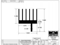
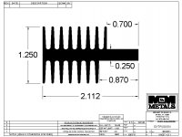
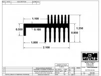
Do you all agree on heat sink #2? One thing I like about heat sink 3 is the mounting foot. This would be one sturdy heatsink screwed down to the board itself. Heatsink #2 is also a litle short on mounting ares as far as height goes. I can live with either but I wanted to bring up the mounting foot point. Let me know which one and I will e-mail M&M for pricing on six- 6 foot extrusions of the one we all agree on by Monday. I think six- 6 foot extrusions should be enough for 50 boards. I have a horizontal band saw at my disposal at work so I can also slice them to the finished board width.
Note that heatsink 2 is 2.8 deg C/W and three is 2.6 deg c/w... surprisingly it's slightly better.
Mark
PWatts,
A comment to placement of the cascaded transistors: you could buy cheap heat sinks on eBay. It will be hard to fit a single heat sink on each transistor, they are placed to close to each other, if using those cheap heat sinks (look at picture)
Is it possible to make more space between those transistors (including two holes for screws as in the original KRELL), or are you only thinking of one large sink (if yes you most add some isolation between each transistor and the sink, also some holes for two fixing screws).
Regarding 7) yes add a fourth support hole to the LTP transistor foot print (Guess there is a lot of members who has the 2S-type transistor in stock)
Regards
Attachments
- Home
- Amplifiers
- Solid State
- Krell KSA 100mkII Clone