I have an opportunity to pick up an Ampliwire 100 with a shorting problem. Doing a quick take I was able to determine that the problem is from the right channel after the power supply. By any chance does anyone know if this particular model amp is plagued with problems? A few folks seem to think so - I just do not have much history on its reliability.
Thank you for the help.
Thank you for the help.
Thank you for the information. I tested a bit further and found the right channed output transistors to be completely shorted - both parallel pairs 2SA1141 & 2SC2681 - also two 2SA1141 transistors on the driver board are shorted. I do not see visual signs of heat stress and am unsure at this point what event provoked the failure.
I seethat NEC transistors were used and would like to replace with the the same. The challenge now is to find the original OEM parts (prefered over NTE). Any suggestions?
Thanks - off to a good start.
I seethat NEC transistors were used and would like to replace with the the same. The challenge now is to find the original OEM parts (prefered over NTE). Any suggestions?
Thanks - off to a good start.
rollo22
I used a series lamp in line with the power and dummy loads for the speakers. On my unit the lamp had full illumination (shorted) so I removed both L&R channels - tested the power rails (good) and replaced the channels one at a time and determined the right channel was shorted. I found four 2SA1141 and two 2SC2681 shorted - replaced them tested the bias and found it climbing as the unit warmed. Alas the culprit - the thermal sensing transistor mounted on the heat sink. It used a thermal blanket (not good) so I tried a mica and the bias is now rock steady. hope this helps.
nuvo
Hello Nuvo
I am glad you succeded...
my case is more difficult for me, I have problems in the input stage so far.
In particular the offset at JP1 ( between the input and the output stage)
is very variable from -10V at turn on until +.6V to -.9V when warm ( to me it
looks like a temp related slow oscillation, but maybe it is normal ) .
To test I cut JP1 and put a 4K7 resistor to ground as per suggestion in schematics.
How was your JP1 Voltage settling and stability ?
I wonder if you could help me in saying (if you feel like) what are the steady voltages at some points in the circuit.
If you can, then, I would need the voltages at R5, R6, R11, R12, R13, R14 for the Input stage
and then R5, R6, R11, R12 for the ouput stage.
I understand that it would be a pain to open a working amp again but I would appreciate any help I can get.
BTW where did you find the 2SC2681/2SA1141 ?
Best regards
Rollo
rollo22
I will open the amp sometime over the weekend and get you the readings. Just not sure your designations match what I am working from. I got the schematic from another DIY - do not remember the name off hand but I will look it up so you can see the same print. BTW - just make sure the TO-92 transistors mounted on the large heat sink is snugged - a loose one may give you some thermal (voltage) variance.
Parts - I bought from consolidated electronics - www.ceitron.com - but he did not have all I needed and I had to buy some NTE replacements.
nuvo
I've managed to get the schematics from Andrea's homepage, the complete service manual is no longer present.
It would be nice if you could post the rail voltages, VCC and VDD on the AW-100 schematic.
The AW-100 schematic only has 1 pair of Toshiba 2SA1095/2SC2565 in the output stage. I remember it having 2 sets, as confirmed by Nuvo. Does the parallel output device set on the AW-100 have emitter resistors ?
1st series AW-250DMB had 12 of those ring-emitter output devices per channel.
2SA1141 are still available, sometimes for a dollar the piece, 2SC2681 is very hard to find.
Sanken 2SA1186/2SC2837 are easily obtainable replacements for the NEC devices.
Hi Nuvo
thanks very much for your help.
I don't have any TO92 on the heatsink, only the Q10 TO126 for the
Bias function is on the heatsink ...
for Jacco
I tried to draw a schematics of the AW65 output side but
got problems in saving it, the input side is here --->>
http://www.diyaudio.com/forums/showthread.php?postid=880190#post880190
Regards
PS the files I have are too big for this site...
AW100 readings
rollo
My amp is an early AW100 so it does not match the schematic at Andypairo's site exacxly. What I will try
is to match the readings to your schematic, so bear with me and I hope I get it right:
readings taken - no signal input - 8 ohm speaker load
power readings at the connection terminal on the signal PCB
+Vdd = 55.0v
-Vdd = 54.7v
+Vcc = 44.1v
-Vcc = 43.9v
Input signal section - emitter resistor voltage drop (polarity not observed)
Q1/Q2 -> R2 & R3 = 3.1v
Q10/Q11 (2SA1184) -> 8.64v & 8.5v temp 165F
Q8 & Q9 (2SA2824) -> 10.4v & 10.4v temp 171F
Q5 -> R7 = 9.8v
BTW - check the base voltage for Q5 - I believe it should be 10v - if this
fluxuates then it will affect Q1, Q2, Q3, Q4
I adjustd the output emitter resistors to draw about 12ma (9mv on my amp) - temp runs
between 90F to 111F
Class A amps do run hot, but the AW series seems to test ones nerves.
nuvo
Thanks a lot for your help Nuvo !
the readings are not too far from mine, I checked Q5, it seems to be steady.
I think that there are variations of gain with
temp in the stages leading to JP1 which
make it oscillating... (and yet I matched them with a curve tracer)
Was your JP1 steady ?
BTW are R17/R18 500ohms for your Amp ?
Best regards
Rollo
PS did you take a picture of the boards ?
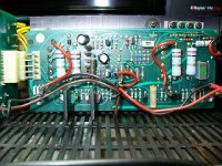
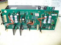
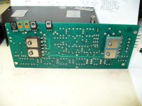
rollo;
pic of the main input board - notive the TO 90 types in the upper right affixed to the heat sink - makw sure these are snug. The tO 90 type just to the left of the four in a row is the thermal bias control for the optput transistors - notice the mica? This is what is needed in this position.
pic of the main input board - notive the TO 90 types in the upper right affixed to the heat sink - makw sure these are snug. The tO 90 type just to the left of the four in a row is the thermal bias control for the optput transistors - notice the mica? This is what is needed in this position.
Attachments
- Status
- This old topic is closed. If you want to reopen this topic, contact a moderator using the "Report Post" button.
- Home
- Amplifiers
- Solid State
- Electrocompaniet Ampliwire 100