Hello everyone,
Well i guess this is the right forum for my topic.
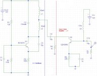
I have attached ckt diag of an FM oscillator coupled to something which i tend to call as an UNKNOWN TYPE of RF Amplifier..
I/p is provided to the collector, and o/p taken from the base.. Sounds bad, atleast to me.. I have used this part of the circuit in constructing my first FM Transmitter. The complete ckt consists of a final class C power amp (2n3866) with a stated o/p of around 1WATT, and is driven by the o/p available with the circuit that have attached with this post.
The device works, but not as completely as it should. I certainly get very little power o/p with a range of around 10-15 meters indoor, using a 100cm aerial. Clarity and freq stability is good.
I havent designed this circuit. Just tried to implement it for fun. Since it works below par, i m now trying to analyze it.
If anyone can help me to understand that "alien" class C dirve amp., then pls reply back.
Thanks in advance.
Regards, Prasanna Prithviraj.
____________________________
Well i guess this is the right forum for my topic.
I have attached ckt diag of an FM oscillator coupled to something which i tend to call as an UNKNOWN TYPE of RF Amplifier..
I/p is provided to the collector, and o/p taken from the base.. Sounds bad, atleast to me.. I have used this part of the circuit in constructing my first FM Transmitter. The complete ckt consists of a final class C power amp (2n3866) with a stated o/p of around 1WATT, and is driven by the o/p available with the circuit that have attached with this post.
The device works, but not as completely as it should. I certainly get very little power o/p with a range of around 10-15 meters indoor, using a 100cm aerial. Clarity and freq stability is good.
I havent designed this circuit. Just tried to implement it for fun. Since it works below par, i m now trying to analyze it.
If anyone can help me to understand that "alien" class C dirve amp., then pls reply back.
Thanks in advance.
Regards, Prasanna Prithviraj.
____________________________
Attachments
Agreed! I once built a 1W FM band 2 transmitter about 20 years ago, It could be received up to 4 miles away on a good day and in the direction that favoured good propagation!
The only thing I have seen that could be remotely like that circuit could be a parametric (varactor) power frequency doubler.....but then again....
The only thing I have seen that could be remotely like that circuit could be a parametric (varactor) power frequency doubler.....but then again....
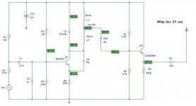
COMPLETE TRANSMITTER CIRCUIT POSTED HERE.
Thanks for the reply. So, i have modified the amplification section be simply using a Class A emiiter follower. The AC power dissipated by the load RE is about 200 mW at 12 Volts Vcc. I have posted the complete circuit here.
However, the range has not improved at all. Is there a problem in the antenna coupling ckt. (i havent used much of it eighter)..?
Waiting for a response..
Regards Prasanna Prithviraj.
Re: COMPLETE TRANSMITTER CIRCUIT POSTED HERE.
An emitter follower gives no voltage gain, so you're not improving anything (apart from warming a resistor). It's usual to use a class C amplifier with a tuned collector loading coil, probably with a tap to match the impedance of the aerial.
Have a look here for an example.
xitronics said:Thanks for the reply. So, i have modified the amplification section be simply using a Class A emiiter follower. The AC power dissipated by the load RE is about 200 mW at 12 Volts Vcc. I have posted the complete circuit here.
However, the range has not improved at all. Is there a problem in the antenna coupling ckt. (i havent used much of it eighter)..?
An emitter follower gives no voltage gain, so you're not improving anything (apart from warming a resistor). It's usual to use a class C amplifier with a tuned collector loading coil, probably with a tap to match the impedance of the aerial.
Have a look here for an example.
A few random thoughts:
Is 75cm a quarter wavelength antenna at your operating frequency? If so I take it you’re operating at approximately 400MHz. I hope your not doing this on a breadboard… For an FM system I think a Class-C amplifier will be the way to go [75% eff. Max]. When you design the input stage of your amplifier make sure it has an input impedance of at least 50-Ohms otherwise you could kill your oscillator by loading it down too hard. A 50-Ohm impedance matching band-pass filter on the output would also be wise.
Regards,
-=Randy
Mankato MN
HOW IS THE APPROX. EVALUATION OF RF POWER GENERATED DONE..?
Dear Sir,
Firstly I would like to thank you all for the patience and the worthy ideas given to me.
Alright, I would use an LC tuned ckt for the final stage. But how can i approximately calculate the RF power that the final stage would provide, as i may require that during designing.
As one final question sir.. My receiver detects the transmitted information at about 3-4 different frequencies (even though the reception at all; expect my actual transmitting frequency would completely vanish if i move 4-5 mtrs away from the Tx). Is it due to my cheap BC547 having slightly less Ro, which destroys the Q factor of the LC tank..?
Hoping for some suggesstions here.
_____________________
Thanks in advance,
Regds., Prasanna Prithviraj.
Nigel Goodwin said:
It's usual to use a class C amplifier with a tuned collector loading coil, probably with a tap to match the impedance of the aerial.
Dear Sir,
Firstly I would like to thank you all for the patience and the worthy ideas given to me.
Alright, I would use an LC tuned ckt for the final stage. But how can i approximately calculate the RF power that the final stage would provide, as i may require that during designing.
As one final question sir.. My receiver detects the transmitted information at about 3-4 different frequencies (even though the reception at all; expect my actual transmitting frequency would completely vanish if i move 4-5 mtrs away from the Tx). Is it due to my cheap BC547 having slightly less Ro, which destroys the Q factor of the LC tank..?
Hoping for some suggesstions here.
_____________________
Thanks in advance,
Regds., Prasanna Prithviraj.
Re: HOW IS THE APPROX. EVALUATION OF RF POWER GENERATED DONE..?
It's usual to specify the DC input to the output stage, you can measure the current and voltage simply with an ammeter and voltmeter.
If it's transmitting harmonics it may be over driven, but a second tuned RF stage will help to reduce that - but you should also try lowering the first stage, try adjusting the bias conditions.
xitronics said:
Dear Sir,
Firstly I would like to thank you all for the patience and the worthy ideas given to me.
Alright, I would use an LC tuned ckt for the final stage. But how can i approximately calculate the RF power that the final stage would provide, as i may require that during designing.
It's usual to specify the DC input to the output stage, you can measure the current and voltage simply with an ammeter and voltmeter.
As one final question sir.. My receiver detects the transmitted information at about 3-4 different frequencies (even though the reception at all; expect my actual transmitting frequency would completely vanish if i move 4-5 mtrs away from the Tx). Is it due to my cheap BC547 having slightly less Ro, which destroys the Q factor of the LC tank..?
If it's transmitting harmonics it may be over driven, but a second tuned RF stage will help to reduce that - but you should also try lowering the first stage, try adjusting the bias conditions.
Hi!
There are too many problems surprising it does not work. the coupling cap between stages is missing secondly its an emitter follower no gain .
make the o/p class C do a google on veronica and other FM tx design they are proven and good.
Need to transform the O/P impedence to 50 ohms
O/P impedence V*V/2Po
Use LC ratio to match.
This is the finest design that I have made till date as a free running OSC config:
http://www.geocities.com/Area51/Nebula/3736/veronica.htm
Hope it helps
good luck
- Status
- This old topic is closed. If you want to reopen this topic, contact a moderator using the "Report Post" button.
- Home
- Amplifiers
- Solid State
- RF Amplifier Problem