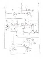
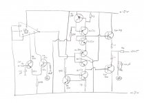
I have a copy of the circuit of the musical fidelity MVT preamp (mk 3) of around 1988. The copy is very bad and therefore I puzzled somewhat and drew the version that I attached with this thread. The MVT did get a lot of positive reviews at that time and I think it must have a lot of potention. Especially the fact that it is a DC-coupled discrete and simple line-stage from input to output seems of interest. Furthermore the output stage is heavily biased in class-A.
I tried to understand and simulate the circuit but have a number of questions where we can help each other out maybe.
The circuit consists of 3 stages, and this is what I make of it:
1. a differential input stage with innovative use of the LM318 IC in order to get around 0 mV at the DC output
2. a midstage with a bc550 (and associated components inclusing constant current source) in the negative rail and a bc560 (and associated components) in the positive rail.
3. an output stage in push-pull using complementary bd139/bd140, class-A.
A few problems and questions:
1. How does the LM318 work in this circuit? I do not have this component in the library of my simulator and therefore did not succeed in checking the workings of the circuit. It seems to me that the use of this piece of electronics is getting a zero offset at the output since no other adjustment is possible in this amp.
2. The midstage seems to be symmetrical but if you look carefully the positive half has an extra bc550. I do not understand this set-up and I am inclined to think it is a deliberate error in the schematic or something special whick indeed I do not understand.
3. In the original circuit bc414/416 are used instead of bc550/560 and bd135/136 instead of bd139/140, but this is of no importance to the questions posed.
4. I did simulate the circuit assuming the input is a normal differential input pair with 47k resistors to the positve power rail and making the midstage symmetrical by leaving the odd bc550 out. In this case the circuit seems to work and has around 20 dB of gain, but 2 transistors in the midstage are idling at around 13 mA of current while the output stage idles at around 4 mA. Well, this is another circuit and my goal is understandig and building the original MVT.
Attachments

OK......
Your first three points,
1/ (and also 1 in your second questions) The LM318 is not used merely as a servo, it is an important part of the design. The unusual way it , at first, appears to be used (your diagram looks correct) is due to the internal input stage being switched off/disconnected by the connection of the inputs to ground. The long tail pair coming from the op-amp pins merely replaces the internal LTP with a much lower noise version (see National Semiconductors "linear handbook" and application notes for the LM318. MF used this lots in various designs)
2/ Yes.
3/ Yes.
Your second list of Q's:
2/ The extra BC550 (diode connected) IS NOT A MISTAKE.
3/Bc416/414 were interchanged with 550/560 all the time at MF, there is no differance to performance. BC214/184 were used in early MVT. Bd139/140 will indeed work fine.
Finally (and I speak from experiance here), the MVT mk2 sounds MUCH better than the mk3. I've just converted my DIY mk3 to mk2 spec after hearing the differance between factory made mk2 and mk3 amps. The mk2 uses the same circuit that your query is about (with some minor variations) BUT it does not use the conventional volume control of the mk3...it uses TL071 series op-amps (I know more silicon in signal path should not be good but it works!) as a buffer and then another as a feedback volume control as used in the A1 etc, this then feeds the stage discussed above. The mk2 has four of the class A stages arranged to provide both inverting and non inverting outputs for each channel. I have built only the inverting ones as I think it sounds a bit better.
Jez.
Your first three points,
1/ (and also 1 in your second questions) The LM318 is not used merely as a servo, it is an important part of the design. The unusual way it , at first, appears to be used (your diagram looks correct) is due to the internal input stage being switched off/disconnected by the connection of the inputs to ground. The long tail pair coming from the op-amp pins merely replaces the internal LTP with a much lower noise version (see National Semiconductors "linear handbook" and application notes for the LM318. MF used this lots in various designs)
2/ Yes.
3/ Yes.
Your second list of Q's:
2/ The extra BC550 (diode connected) IS NOT A MISTAKE.
3/Bc416/414 were interchanged with 550/560 all the time at MF, there is no differance to performance. BC214/184 were used in early MVT. Bd139/140 will indeed work fine.
Finally (and I speak from experiance here), the MVT mk2 sounds MUCH better than the mk3. I've just converted my DIY mk3 to mk2 spec after hearing the differance between factory made mk2 and mk3 amps. The mk2 uses the same circuit that your query is about (with some minor variations) BUT it does not use the conventional volume control of the mk3...it uses TL071 series op-amps (I know
more silicon in signal path should not be good but it works!) as a buffer and then another as a feedback volume control as used in the A1 etc, this then feeds the stage discussed above. The mk2 has four of the class A stages arranged to provide both inverting and non inverting outputs for each channel. I have built only the inverting ones as I think it sounds a bit better.Jez.
very interesting indeed
Wow, this is some information. But as usual, new info calls for new questions:
1. How is zero-offset guaranteed for? In your diy version: how does it behave in this respect (is indeed no output cap needed for safety reason when using a DC power amp)?
2. What are the idling current in the output stage and in the mid-stage? Is cooling of some devices necessary?
3. I don't get it that an extra opamp stage better the sound quality of the preamp. Maybe just using the opamps and leaving this circuit out completely is yet the best option, just as in the original A1? Have you tried that? Do you have an explanation for this odd state of affairs?
4. I do not succeed in simulating the circuit with the BC550 as diode. Could it be that this has something to do with not being able to get the LM318 in the circuit or can the midstage be seen as a separate entity that must work anyhow
5. I would greatly appreciate the schematics of your best working version, if needed by personal email. Thanks. Do you have some pictures of the boards, would be nice too!
Re: very interesting indeed
I was waiting for this!!!! I dont have diagrams in electronic form, I would have to scan it and convert to PDF etc.....will try to when I have the time. I did'nt use PCB's for this.rmgvs said:Wow, this is some information. But as usual, new info calls for new questions:
1. How is zero-offset guaranteed for? In your diy version: how does it behave in this respect (is indeed no output cap needed for safety reason when using a DC power amp)?
There is no zero offset guarantee. Use well matched semi's and there will be no problem. (2mV or so.no output cap needed)
2. What are the idling current in the output stage and in the mid-stage? Is cooling of some devices necessary?
No idea. heatsinks are needed for output devices. (did you not have access to one to trace the schematic?)
3. I don't get it that an extra opamp stage better the sound quality of the preamp. Maybe just using the opamps and leaving this circuit out completely is yet the best option, just as in the original A1? Have you tried that? Do you have an explanation for this odd state of affairs?
I don't get it either!, even stranger is that using "better" op-amps than TL0 series gave worse sound!? Yes it occured to me that maybe just the op-amps could sound better still....have'nt tried it yet.
4. I do not succeed in simulating the circuit with the BC550 as diode. Could it be that this has something to do with not being able to get the LM318 in the circuit or can the midstage be seen as a separate entity that must work anyhow
The bc550 (strange isn't it) is probably there to help obtain correct bias for the output stage and/or to compensate for an offset in the output of the LM318 and thereby allow equal +- swing at output.
5. I would greatly appreciate the schematics of your best working version, if needed by personal email. Thanks. Do you have some pictures of the boards, would be nice too!
simulation
I did not see ever a real MVT in life. I via-via got hold of a bad copy of the circuit.
I succeeded in simulating the circuit including the diode-transistor. But only by making a LTP by myself (using 220k en 47k as resistors, else I couldn't get reasonable working) and not by using the intended LM318.
If anybody has a spice-model for the LM318 ....
Then I get the following results:
- total gain is around 21 dB.
- idle current of output stage is 34 mA, dissipation of BD's is 0,6 Watt per device. Not cooling them seems a viable option.
- idle current of BC's (4 of them) in midstage is 14 mA, dissipation 0,23 Watt per device.
LM318N (DIP-8) spice models
Linear Technology LM318N
.SUBCKT LM318 3 2 7 4 6
* INPUT
RC1 7 80 7.074E+02
RC2 7 90 7.074E+02
Q1 80 2 10 QM1
Q2 90 3 11 QM1
C1 80 91 300E-12
RXC1 91 90 1E3
CXC1 91 90 15E-12
C2 1 8 5.000E-12
RB1 2 102 1.0000E+00
RB2 3 103 1.0000E+00
DDM1 102 104 DM2
VZ1 104 103 5.5
DDM2 103 105 DM2
VZ2 105 102 5.5
RE1 10 12 6.209E+02
RE2 11 12 6.209E+02
IEE 12 4 6.000E-04
RE 12 0 3.332E+05
CE 12 0 2.632E-13
GCM 0 8 12 0 1.414E-08
GA 8 0 80 90 1.414E-03
R2 8 0 1.000E+05
GB 1 0 8 0 5.318E+01
RO2 1 0 7.4000E+01
RS 1 6 1
ECL 18 0 1 6 3.172E+01
GCL 0 8 20 0 1
RCL 20 0 1E3
D1 18 20 DM1
D2 20 18 DM1
D3A 131 70 DM3
D3B 13 131 DM3
GPL 0 8 70 7 1
VC 13 6 3.6473
RPLA 7 70 1E4
RPLB 7 131 1E5
D4A 60 141 DM3
D4B 141 14 DM3
GNL 0 8 60 4 1
VE 6 14 3.6473
RNLA 60 4 1E4
RNLB 141 4 1E5
IP 7 4 4.400E-03
DSUB 4 7 DM2
* MODELS
.MODEL QM1 NPN (IS=8.000E-16 BF=1.818E+03)
.MODEL QM2 NPN (IS=9.347E-16 BF=2.222E+03)
.MODEL DM1 D (IS=1.000E-19)
.MODEL DM2 D (IS=8.000E-16)
.MODEL DM3 D (IS=1.000E-20)
.ENDS LM318
National LM318N (L1)
.SUBCKT LM318 1 2 3
* EWB Version 4 - 3 Terminal Opamp Model
* A= 200000 RI= 3e+006 RO= 75 VSW+= 18 VSW-= -18
* Vos= 0.004 Ibs= 1.5e-007 Ios= 3e-008 SR+= 7e+007
* fu= 1e+007 fp2= 1e+032 CC= 3e-011
Vos 4 1 DC 0.004V
Ib1 4 0 1.65e-007A
Ib2 2 0 1.35e-007A
G1 0 5 4 2 0.0584804
G2 0 6 5 0 0.779738
G3 0 3 6 0 0.779738
Ri 4 2 3e+006ohm
R1 5 0 1000ohm
R2 6 0 75ohm
R3 3 0 75ohm
C1 5 0 3.1831e-006
C2 6 0 2.12207e-035
Cc 5 0 3e-011
.ENDS
National LM318N (L2)
.SUBCKT LM318 1 2 3 4 5
* EWB Version 4 - 5 Terminal Opamp Model
* nodes: 3=+ 2=- 1=out 5=V+ 4=V-
* VCC= 20 VEE= -20 CC= 3e-011 A= 200000 RI= 3e+006
* RO= 75 VOS= 0.004 IOS= 3e-008 IBS= 1.5e-007
* VSW+= 18 VSW-= -18 CMMR= 100
* ISC= 0.025 SR= 70 Fu= 1e+007 Pm= 4.35056e-008
VC 5 15 DC 2.61751V
VE 12 4 DC 2.61751V
IEE 10 4 DC 0.0021003A
R1 10 0 10Gohm
R6 11 0 100Kohm
R7 5 4 1Kohm
Rc1 6 5 530.516ohm
Rc2 5 7 530.516ohm
Re1 9 10 505.826ohm
Re2 8 10 505.826ohm
Ro1 1 14 37.5ohm
Ro2 14 0 37.5ohm
Ree 10 0 95224.5ohm
Rcc 0 13 1.57782e-006ohm
Cee 0 10 1e-012
Cc 14 11 3e-011
C1 6 7 1e-016
GA 11 0 6 7 0.00188496
GC 0 13 1 0 633788
GB 14 0 11 0 28.2942
GCM 0 11 10 0 1.88496e-008
D1 14 13 Dopamp1
D2 13 14 Dopamp1
D3 1 15 Dopamp2
D4 12 1 Dopamp2
Qt1 6 2 9 Qopamp1
Qt2 7 3 8 Qopamp2
.MODEL Dopamp1 D (Is=1.05533e-012A Rs=0 Cjo=0F Vj=750mV Tt=0s M=0)
.MODEL Dopamp2 D (Is=8e-016A Rs=0 Cjo=0F Vj=750mV Tt=0s M=0)
.MODEL Qopamp1 NPN (Is=8e-016A BF=6363.64 BR=960m
+ Rb=0ohm Re=0ohm Rc=0ohm Cjs=0F Cje=0F Cjc=0F
+ Vje=750m Vjc=750m Tf=0 Tr=0 mje=0 mjc=0 VA=50)
.MODEL Qopamp2 NPN (Is=9.23791e-016A BF=7777.78 BR=960m
+ Rb=0ohm Re=0ohm Rc=0ohm Cjs=0F Cje=0F Cjc=0F
+ Vje=750m Vjc=750m Tf=0 Tr=0 mje=0 mjc=0 VA=50)
.ENDS
National LM318N (L2A)
.SUBCKT LM318 1 2 99 50 28
*Features:
*Internal frequency compensation
*High bandwidth = 15MHz
*Minimum slew rate = 50V/uS
*Low bias current = 250nA
*Wide supply range = +-5V to +-20V
****************INPUT STAGE**************
IOS 2 1 30N
*^Input offset current
R1 1 3 1.5MEG
R2 3 2 1.5MEG
I1 4 50 100U
R3 99 5 517
R4 99 6 517
Q1 5 2 4 QX
Q2 6 7 4 QX
*Fp2=25 MHz
C4 5 6 6.1569P
***********COMMON MODE EFFECT***********
I2 99 50 4.9M
*^Quiescent supply current
EOS 7 1 POLY(1) 16 49 4E-3 1
*Input offset voltage.^
R8 99 49 80.2K
R9 49 50 80.2K
*********OUTPUT VOLTAGE LIMITING********
V2 99 8 2.63
D1 9 8 DX
D2 10 9 DX
V3 10 50 2.63
**************SECOND STAGE**************
EH 99 98 99 49 1
G1 98 9 POLY(1) 5 6 0 3.0967E-4 0 596.674E-3
*Fp1=115 Hz
R5 98 9 9.6877G
C3 98 9 1.4286P
************POLE/ZERO STAGE*************
*Fp=300 KHz, Fz=600 KHz
G2 98 13 9 49 1E-6
R10 98 13 1MEG
R11 98 14 1MEG
C6 14 13 2.6526E-13
***************POLE STAGE***************
*Fp=55 MHz
G3 98 15 13 49 1E-6
R12 98 15 1MEG
C5 98 15 2.8937E-15
*********COMMON-MODE ZERO STAGE*********
*Fpcm=3 KHz
G4 98 16 3 49 1E-8
L2 98 17 53.1M
R13 17 16 1K
**************OUTPUT STAGE**************
F6 50 99 POLY(1) V6 200U 1
E1 99 23 99 15 1
R16 24 23 30
D5 26 24 DX
V6 26 22 .63V
R17 23 25 30
D6 25 27 DX
V7 22 27 .63V
C9 23 22 100P
V5 22 21 0.2V
D4 21 15 DX
V4 20 22 0.2V
D3 15 20 DX
L3 22 28 100P
RL3 22 28 100K
***************MODELS USED**************
.MODEL DX D(IS=1E-15)
.MODEL QX NPN(BF=333.333)
.ENDS
TI LM318N (L1)
.SUBCKT LM318 1 2 3
* EWB Version 4 - 3 Terminal Opamp Model
* A= 200000 RI= 3e+006 RO= 75 VSW+= 13 VSW-= -13
* Vos= 0.004 Ibs= 1.2e-007 Ios= 3e-008 SR+= 7e+007
* fu= 1.5e+007 fp2= 1e+032 CC= 1e-011
Vos 4 1 DC 0.004V
Ib1 4 0 1.35e-007A
Ib2 2 0 1.05e-007A
G1 0 5 4 2 0.0584804
G2 0 6 5 0 0.779738
G3 0 3 6 0 0.779738
Ri 4 2 3e+006ohm
R1 5 0 1000ohm
R2 6 0 75ohm
R3 3 0 75ohm
C1 5 0 2.12207e-006
C2 6 0 2.12207e-035
Cc 5 0 1e-011
.ENDS
TI LM318N (L2)
.SUBCKT LM318 1 2 3 4 5
c1 11 12 8.50E-12
c2 6 7 25.00E-12
dc 5 53 dx
de 54 5 dx
dlp 90 91 dx
dln 92 90 dx
dp 4 3 dx
egnd 99 0 poly(2) (3,0) (4,0) 0 .5 .5
fb 7 99 poly(5) vb vc ve vlp vln 0 1.697E6 -2E6 2E6 2E6 -2E6
ga 6 0 11 12 2.474E-3
gcm 0 6 10 99 13.25E-9
iee 10 4 dc 1.750E-3
hlim 90 0 vlim 1K
q1 11 2 13 qx
q2 12 1 14 qx
r2 6 9 100.0E3
rc1 3 11 424.4
rc2 3 12 424.4
re1 13 10 394.7
re2 14 10 394.7
ree 10 99 114.3E3
ro1 8 5 50
ro2 7 99 50
rp 3 4 9.231E3
vb 9 0 dc 0
vc 3 53 dc 2.700
ve 54 4 dc 2.700
vlim 7 8 dc 0
vlp 91 0 dc 21
vln 0 92 dc 21
.MODEL dx D(Is=800.0E-18)
.MODEL qx NPN(Is=800.0E-18 Bf=5.833E3)
.ends
At least one of these should work...
Regards, a
spice
Thanks a lot for the models.
I'm wondering: in the circuit the LM318 uses 7 different pins while all models I see only have 3-5 pins modelled.
On the other hand, I have no experience with adding models of my own to the library. I use LT spice and it looks easy enough to add a .lib file with the model description. But to add a picture with pin numbers and a drawing the program works with .asy files that are of different order and no other model avaible uses 7 pins as in the LM318.
As I understand it now I need a .lib file (that I can make myself using the information above, be it that I have the question of the 7 pins) and I need a .asy file that makes the drawing and translates between the drawing and the computation of the model.
That's how it goes: I just want to understand a particular circuit and before I know I'm becoming a specialist in programming spice models ...")
Thanks a lot for the models.
I'm wondering: in the circuit the LM318 uses 7 different pins while all models I see only have 3-5 pins modelled.
On the other hand, I have no experience with adding models of my own to the library. I use LT spice and it looks easy enough to add a .lib file with the model description. But to add a picture with pin numbers and a drawing the program works with .asy files that are of different order and no other model avaible uses 7 pins as in the LM318.
As I understand it now I need a .lib file (that I can make myself using the information above, be it that I have the question of the 7 pins) and I need a .asy file that makes the drawing and translates between the drawing and the computation of the model.
That's how it goes: I just want to understand a particular circuit and before I know I'm becoming a specialist in programming spice models ...
How (exactly) should we improve our Mk3s...?
I have an MVT Mk3 and though it does some things well, it can be a bit over-smooth and kinda obscures the details - I cant help think though that there is a fantastic pre-amp in there just desperate to get out...
I say this as despite fitting better quality 3-pin regs (not done the negative supply yet though, I'll get round to it...) better film caps and electrolitics, that fundamentally over-smooth character remains. I've been meaning to upgrade the pot for a while now and will now definately get on with that.
I am curious about the LM318 though can anyone recommend a replacement which might open the sound of the pre-amp up a bit....?
jez said:.
P.S. MVT= (I am fairly confident) Micheal Vaughn Thomas, also designer of the Dr. Thomas power amp and original "The Preamp" from MF....just for info
Because Anthony Michaelson can't design a sausage.
Replacing the LM318 - Worthwhile?
Would the connection arrangement that sees the op-amp's internal LTP disabled, allowing the use of a lower noise, all discrete version work with any op-amp? (With pins 1, 5 and 8 simply bent out of the way).
I have BB627s, BB604s, LT1028s, etc, here and want to see if I can lift someof the veiling using one of those...
Any help would be much appreciated...
But can I use ANY op-amp?
Yes, so I understand, but in the MVT circuit arrangement, the op-amp's internal LTP is disabled anyhow, removing (I guess) much of the voltage noise advantage the LT1028 would have over its rivals.
I'm just keen to know if ANY op-amp cam be used (with pins 1, 5 and 8 simply bent out of the way (as the compensation components required for the LM318 aren't required).
These experiments with op-amp substitution (along with the pot replacement and taking the balance control out of circuit) will really be the last straw with this incredibly frustrating preamp. The phono stage (which incredibly, no-one has mentioned) is, quite simply, sublime. I dont want to change, but despite a far bigger and berret toroidial transformer, better regs, approximately 40 (thats right) Black Gates, upgraded film caps, etc I just havent been able to achieve the open, completely transparent sound I'm after.
(I've also got a pair of Mk1 P270s with the same front end, so I'll be looking to experiment their too)
again replacement question
Though this topic seems to be dead, I keep having the question about the possible replacement of the LM318 into the MVT. Looking at the pin numbers and their function for instance the common NE5534 would be a good choice, but after trying this it does not work out.
Can anybody explain this? Is the 318 different and not compatible with standard single opamps like 5534? If so (which I think has been proven by my experiment) what opamp/ic can be used as a direct replacement (without bending of cutting off legs)?
Got it working
After some years of having the first idea of building this circuit, I final;ly did. An d with good results. Some things for possible followers of doing this tric:
1. I also got the old original factory made model, mk II.
2. So I was able to compare some things.
3. The diy version can be got on a similar level of performance.
4. Remember: Martin Colloms in HFNRR of circa 1988 listened to this design and his conclusion at the time was: probably the best preamp ever made in the UK and very close to at that time US tube kings like Audio Research SP-9.
5. I did not succeed in getting to work it with another opamp as LM318.
6. The circuit as I gave it a few posts before is allright, it works as is (careful with layout and wire, oscillation is quick to arrive).
7. Idle currents are as simulated by me: around 30 mA for the output stage, around 15 mA for the midstage. Cooling of the bd's seems a wise thing, some small pieces of aluminium will do. Idle current can be got down a little by making the output resistors somewhat bigger (18 ohms for example), this will do the sound no harm (as far as I can hear).
8. The miracle of getting the offset to zero: this does not exist. The factory model has a few Millivolts on the one channel, but around 10-20 on the other. So they at MF have probably chosen the LM318 and components to get around 0 mV but there is not an automatic rule that you will get that. You can put a potmeter of 1k in the LTP (instead of the 560 resistors) and turn it to get 0 mV. I reckon this setup is NOT safe for pure DC power amps though (factory model or not). I advice to use a good quality cap at the output (I use 10 mF with good results).
All in all a very good preamp. I also built all kind of different stuff during the last years. A Marantz copy, a Mark Levinson JC-2 and I can't remember what else (Chinese made pcb's are availlable in abundance to experiment with). only a carefully chosen opamp with diamond buffer comes close or is of the same audiophile quality level in my subjective listening experience.
Very high quality transistor preamp circuits (cheap to make, easy to get components, durable etc) are scarce and difficult to find. And this model will drive any poweramp and any length of cable with great ease.
So, what are you waiting for? Take that soldering iron out of the drawer!
Hello
Very nice, it's remember me a phono preamp using the LM318 but at pin 1 and 5 it use a super-matched LM394 transistors pair.
The LM318 are a fast video op-amp with no rise of distortions in high frequency or at very low level, it's an old but unique op-amp, but it's also a noisy op-amp, so by using an external LTP input you keep the speed but not the noise.
Have you try the first version of the Tomlinson Holman preamp or a diy Pass Lab preamp ?
Bye
Gaetan
- Status
- This old topic is closed. If you want to reopen this topic, contact a moderator using the "Report Post" button.
- Home
- Amplifiers
- Solid State
- Musical Fidelity MVT mk3 preamp line-stage