Here's my latest project nearing an end I'm happy to
say after several weeks of working with many different
designs and board layouts. I soon will be building
seven of them for my home theater systems. The design
itself has been posted on this forum before, though
the values may differ some. My objective for this
project was to find a simple Class A/B design with
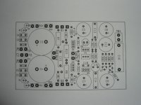
a low parts count, that would allow me to fit over sized caps plus power supply caps on a small board for my home theater amp. Of course it had to have great stability and sound. I think exceeded my expectations by far. The board measures 4.8"x2.95" or 122 x 75mm. Depending on the voltage of the power supply caps the amplifier can run on +/-50v rails for 100 watts into 8 ohms or +/-42v for 60 watts.
I call it a killer little amp because of the way it
performs, and measures. I compared it to three 100
watt amps that use 4 output transistor versus the KLAs two.In a blinded A/B test with three separate subjects using a broad range of music the KLA was selected 80% percent of the time. And it was preferred 100% for it's bass, which I found interesting considering my speakers are rated at 4 ohms, and dips to 3.6 ohms at DC. The amps were running using 42 volt rails, with 50 volt rails the THD is lower, but not by much.
After how well it performed I decided to check it out
on the scope, check it's THD, and anything else that
might explain why it stood out.
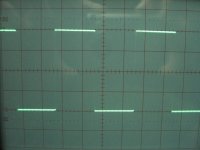
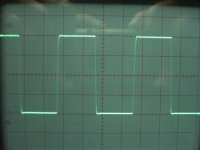
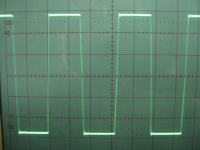
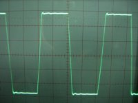
The first thing I found is that the amp doesn't need
an L/R on the output. It handles reactive loads with
ease. I'll post some pics at 10Khz @ 10 watts with 8
ohms||2uf cap. I even tried 100 watts at 20 Khz with
8||4.7uF for a second or two and it held up.
The amp has an output resistance of 0.005ohms for a
damping factor of 1600 into 8 ohms at 1Khz.
It's frequency response is down 3db at 220Khz at 1
watt.
The S/N < 100db
It's THD measures using 50 volts rails as follows:
8 ohms/50 watts @ 1Khz, THD = 0.008%
4 ohms/100 watts @ 1Khz, THD = 0.01%
8 ohms/100 watts @ 1Khz, THD = 0.02%
These measurements look really good, and tells part of
the story as to why the amp sounds so good. The major
factor I believe is the board layout. Also I used high
quality Nichicon ES/FG caps, and a Auricap input cap. But the board layout is key, having the power supply caps on the board allows for a short speaker ground connection which I believe makes a big difference. I always wondered why I don't see more amplifier kits with power supply caps on board. If done correctly it makes a lot sense. Anyway,
I'd love to here from the experts out here as to what
they think.
I'll be placing in order shortly for my home theater
amplifier, and I should have some extra boards available very anybody interested.
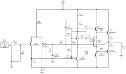
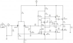
Here's the schematic without the signal ac filter caps or power supply caps. I also snubberized the power supply. I'm not sure if it made differnce but figured I had the room so why not. I'll post some waveform pics shortly.
Best regards,
Al
say after several weeks of working with many different
designs and board layouts. I soon will be building
seven of them for my home theater systems. The design
itself has been posted on this forum before, though
the values may differ some. My objective for this
project was to find a simple Class A/B design with
a low parts count, that would allow me to fit over sized caps plus power supply caps on a small board for my home theater amp. Of course it had to have great stability and sound. I think exceeded my expectations by far. The board measures 4.8"x2.95" or 122 x 75mm. Depending on the voltage of the power supply caps the amplifier can run on +/-50v rails for 100 watts into 8 ohms or +/-42v for 60 watts.
I call it a killer little amp because of the way it
performs, and measures. I compared it to three 100
watt amps that use 4 output transistor versus the KLAs two.In a blinded A/B test with three separate subjects using a broad range of music the KLA was selected 80% percent of the time. And it was preferred 100% for it's bass, which I found interesting considering my speakers are rated at 4 ohms, and dips to 3.6 ohms at DC. The amps were running using 42 volt rails, with 50 volt rails the THD is lower, but not by much.
After how well it performed I decided to check it out
on the scope, check it's THD, and anything else that
might explain why it stood out.
The first thing I found is that the amp doesn't need
an L/R on the output. It handles reactive loads with
ease. I'll post some pics at 10Khz @ 10 watts with 8
ohms||2uf cap. I even tried 100 watts at 20 Khz with
8||4.7uF for a second or two and it held up.
The amp has an output resistance of 0.005ohms for a
damping factor of 1600 into 8 ohms at 1Khz.
It's frequency response is down 3db at 220Khz at 1
watt.
The S/N < 100db
It's THD measures using 50 volts rails as follows:
8 ohms/50 watts @ 1Khz, THD = 0.008%
4 ohms/100 watts @ 1Khz, THD = 0.01%
8 ohms/100 watts @ 1Khz, THD = 0.02%
These measurements look really good, and tells part of
the story as to why the amp sounds so good. The major
factor I believe is the board layout. Also I used high
quality Nichicon ES/FG caps, and a Auricap input cap. But the board layout is key, having the power supply caps on the board allows for a short speaker ground connection which I believe makes a big difference. I always wondered why I don't see more amplifier kits with power supply caps on board. If done correctly it makes a lot sense. Anyway,
I'd love to here from the experts out here as to what
they think.
I'll be placing in order shortly for my home theater
amplifier, and I should have some extra boards available very anybody interested.
Here's the schematic without the signal ac filter caps or power supply caps. I also snubberized the power supply. I'm not sure if it made differnce but figured I had the room so why not. I'll post some waveform pics shortly.
Best regards,
Al
Attachments
Last edited:
Excellent work. Looks like a nice little project, though I hope you're going to heatsink those poor output trannies well. ")
I'd be tempted to give it a go, but for two reaons I can't:
A) I have too many projects on the go already
B) I have far too many projects on the go already!
Still, maybe one day...
I'd be tempted to give it a go, but for two reaons I can't:
A) I have too many projects on the go already
B) I have far too many projects on the go already!
Still, maybe one day...

Hi darkfenriz,
I tried several current sources, my selection of using a resistor to set the current was based on what sounded better to me, and my test subjects. The amp is extremely quiet. With the inputs grounded and my ears just touching the woofers dust caps the amp is dead quiet, and a barely audible hiss on the tweeter.
I tried several current sources, my selection of using a resistor to set the current was based on what sounded better to me, and my test subjects. The amp is extremely quiet. With the inputs grounded and my ears just touching the woofers dust caps the amp is dead quiet, and a barely audible hiss on the tweeter.
hi AAK,
I'm sure this amp sounds pretty good because it is very similar to the Baby AKSA schematic posted here a year or 2 ago. It even has one or 2 components that was missing from the "conceptual" AKSA schematic.
I am curious how you get away with 50v rails where most people using single 2SC5200/2SA1943 output devices recommend 35v for 4 ohms speakers. e.g. AKSA 55, Symasym and P3A.
regards
I'm sure this amp sounds pretty good because it is very similar to the Baby AKSA schematic posted here a year or 2 ago.
It even has one or 2 components that was missing from the "conceptual" AKSA schematic.I am curious how you get away with 50v rails where most people using single 2SC5200/2SA1943 output devices recommend 35v for 4 ohms speakers. e.g. AKSA 55, Symasym and P3A.
regards
One pair of 2sa1943/c5200 on +-50V rails producing 100W into 8r, now that really is a surprise.
I dont think its a surprise.....
Genuine Toshiba pairs are capable of delivering 100W into 4/8 ohms if implemented properly.....I have seen them in various products....In one pro-amp they used 4 pairs to get 550W @4 ohms with VCC at +-85VDC
K a n w a r
Hi workhorse,
you must have a different definition of reliable from me.
I see a pair of 2sa1943/c5200 driving 8ohms to 100W at a phase anle of 45degrees is right on the 100mS SOAR at Tc=35degC.
It has to come down to 30 phase angle to stay within the DC SOAR.
I could not recommend that for any DIYer never mind a commercial unit with a realistic warranty.
That 550W into 4ohm PA you referred to is even worse.
Four pair can only manage 16degree phase angle at Tc=45degC at the 100mS SOAR.
Workhorse said:I have seen them in various products....In one pro-amp they used 4 pairs to get 550W @4 ohms with VCC at +-85VDC
C'mon K a n w a r,
You know far better than I that a simple circuit like this can't safely use 50v rails in a lots of situations. The pro-amps you are talking about would have all kinds of SOAR protection circuitry for circumstances when it is overloaded.
I have an amp with one pair of these devices with 44 volt rails and SOAR protection. I have heard of these amps shutting down the output devices when overdriven but I have not personally experienced it myself. This amp also runs a lot hotter than my 35v amps with the same output devices.
Would you like to clarify?
EDIT: Andrew, looks like you type a lot faster than me.
regards
You all seem to have lots of money for using always a dozen pairs of output devices, (preferably $20/each MOSFETs). It seems like none of you has actually tried a single pair of output devices with increasing rails and decreasing loads in order to get a real reliability reference.
However, there are humble people with little budget like me that enjoy these tests. According to my experience, I would regard a pair of 2SC5200 and 2SA1943 as more than reliable with +-50V rails for music signals. Even at 4 ohms, a -6dB square wave or a sine into a plain capacitor would be required to reach thermal damage or secondary breakdown.
Just as a reference, these are some setups that I was absolutely unable to blow with music signals:
- A single pair of TIP35C/TIP36C with +-45V regulated rails, using a CFP Vbe multiplier to set bias properly and a 4 ohm reactive load (+/-45 degrees). The special Vbe multiplier is required because these transistors feature lower than usual Vbe and higher temperature coefficient.
- A single pair of IRF540/IRF9540 with +-24V regulated rails and the same load (I have yet to try +-40V rails with these).
- Two pairs of 2SC3264/2SA1295 with +-85V slightly sagging rails and the same reactive load.
Assume proper heatsinking and cooling in all cases.
- Status
- This old topic is closed. If you want to reopen this topic, contact a moderator using the "Report Post" button.
- Home
- Amplifiers
- Solid State
- My Killer Little Amp