msamkl said:Does anybody have a DC Protection schematic for Power amps?
I've built Gregs GB150D amp and I'd like to add a circuit to provide Dc protection to the loudspeakers...
Thanks in advance.
Thanasis.
The simplest way to do that is using a servo for which there are many circuits around. More complicated arrangements use a comparator that in the presence of dc offset, will shut down the power to the amp.
I've tried Rods http://sound.westhost.com/project33.htm
and it worked out real nice.
and it worked out real nice.
Hi
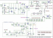
Here is a DC protection that latches when Vdc at power amp output. IN addition there is an "in-rush" circuit (in bonus). It is incorporated in my power amp (I have 2 x 500 VA transfo).
When DC voltage reaches the threshold (+/- 3 V) RL2 contact opens then power voltage for output section is disconnected. RL3 makes the circuit to latch. You need a separate power supply for the detection circuit (same as for the audio driver circuit of the power amp). You may have to adjust components values to suit your amp voltages
It has worked fine since it is installed.
Good luck
Attachments
I have always liked the Hafler DH500 circuit.
I used to buy the board and use them in many other amplifiers (Adcom GFA555, DIY, etc).
http://www.hafler.com/techsupport/pdf/DH-500_amp_man.pdf
PC-9C board on page 16.
An inexpensive LM339 is the heart of the circuit. A couple of resistors set the DC trip voltage, turn-on delay, and it has a quick drop-out on power off. One resistor sets the relay voltage, I've used both 24V and 48V relays with a wide range of B+ voltages. A seperate supply is not needed. I use with a three pole relay, the third contact is used to short out an inrush current limiter.
The foil layout for the PC-9C is on page 19, it could be made smaller too.
Like to look at this one ?
http://users.otenet.gr/~athsam/protection_2_EN.htm
I had some pcb for it (stereo)
http://users.otenet.gr/~athsam/protection_2_EN.htm
I had some pcb for it (stereo)
http://www.richie00boy.pwp.blueyonder.co.uk/images/diyaudio/dc_protect_schematic_small.png
SCHEMATIC COPYRIGHT VELLEMAN
good n simple one.giving active service.
SCHEMATIC COPYRIGHT VELLEMAN
good n simple one.giving active service.
"Small comment: if you want to preserve the maximum damping of your amp"
Considering that this has no effect on how the bass sounds on an amplifier, I would rather have a relay (treated with de-oxit and a small bypass cap).
My McIntosh MC2120 has a DF of 14, and sounds tighter in the bass than direct-coupled high feedback designs that have DF in the hundreds, if not thousands.
DF is a huge red-herring.
Thank you all for your help. I agree that using such a circuit the quality of the sound might be degraded, especially when the relay gets old. I like the schematic on post 4 but it is very complicate for me. If I find someone to help me with the pcb layout, I'll definetely use this one. Of course more suggestions are always welcomed. Are all the circuits using Relays to disconnect the loudspeakers? Isn't there any other way to do this instead of relays?( a Transistor, perhaps, that will act as a switch and cutoff the connection to the loudspeakers when DC appears...)
Forgive me if this is a silly question...I don't know much about electronics.
Thanasis.
Forgive me if this is a silly question...I don't know much about electronics.
Thanasis.
Hi,
do not put an in line series transistor(FET or BJT) as a feed point for the output.
You can, if designed correctly, put a transistor or Diac/Triac from line out to ground that does not affect the sound quality.
If the gound connected transistor switch shorts output to ground you rely on an upstream circuit breaker to isolate the PSU from the output. This crowbar can be effective but it forms a latching cut-off that needs intervention to make the amp live again (or very complicated to achieve auto unlatching).
Is there any great flaw to the rectifer and single detection transistor method, as shown in http://www.ampslab.com/Images/dcpro/dcpro_schema.gif ?
I'm planning to use a similar circuit on my own amp. These other DC detectors seem a lot more complex and I'm wondering why.
I'm planning to use a similar circuit on my own amp. These other DC detectors seem a lot more complex and I'm wondering why.
That circuit draws a relatively large amount of power from the speaker audio to operate properly (as compared to other approaches), so the concern is that it might affect the sound. However, the difference may not be noticeable. Try it. You might start by wiring up the first part only (up to and including Q1, R3, C3 and the +24V supply).jaycee said:Is there any great flaw to the rectifer and single detection transistor method, as shown in http://www.ampslab.com/Images/dcpro/dcpro_schema.gif ?
The basic idea behind
http://www.ampslab.com/Images/dcpro/dcpro_schema.gif
is OK, but there is room for improvement. I prefer a multi-pole low-pass filter on the input, like the circuit from fab, or the three-pole Hafler circuit. Note that the Hafler circuit uses un-equal value resistors for the first stage of the integrator. This allows operation even if one channel goes to the positive rail, and the other fails to the negative rail.
I also like the level shift diode (D7) in the circuit from fab, and his timing cap discharge diode (D5). D5 comes in handy if the power is intermittent, otherwise you lose the subsequent RC timing cycle. Wish I had this a couple of times, it would have been a lot easier on the ears.
The three transistor DC detect portion of the circuit from fab is very similar to the one used by SAE.
msamkl said:Thank you all for your help. I agree that using such a circuit the quality of the sound might be degraded, especially when the relay gets old. I like the schematic on post 4 but it is very complicate for me. If I find someone to help me with the pcb layout, I'll definetely use this one. Of course more suggestions are always welcomed. Are all the circuits using Relays to disconnect the loudspeakers? Isn't there any other way to do this instead of relays?( a Transistor, perhaps, that will act as a switch and cutoff the connection to the loudspeakers when DC appears...)
Forgive me if this is a silly question...I don't know much about electronics.
Thanasis.
Hi Thanasis,
The circuit is quite simple in fact but there is more than DC protection there. It includes several functions like: DC protection, Turn-on delay, thermal protection, in-rush limiting circuit, external control activation, ...For the pcb, I have one pcb layout that integrates all functions so maybe more that you need...Also, I made a few mistakes and I had to "rework" the pcb so I do not have a clean updated pcb layout.
Gandalph said:Greetings from Norfolk
I like the idea of the post #4 in this thread, but can you clarify the connectivity / operation of the circuit around Q1, Q2 & Q3. The connections are not clear to me
Richard
Hi Richard,
AS you have noticed the DC detection circuit is in the "dotted" line part of the circuit which triggers the RL2 activation/deactivation and then RL2 contacts remove power to the big output stage transfo. It simply consists of a low pass filter R1, R2, R3, C1 and C2. Q2 is triggered when a positive DC voltage is present and then Q2 turns off Q5 thus allowing Q6 to conduct (2 transistors switch instead of one since the required collector current imposed by the 24 Vdc relay coils) to trigger RL3 and RL4 (RL3 is only used to latch the protection once activated since once the output stage power is removed it would de-activate and then re-activate and so on...). Manual intervention is needed to re-start the amp but most of the time when you have a big DC at output it is because the amp is faulty and need repair... RL24 designation is for the other channel. Q1 is turned on when a negative DC voltage is present which activates Q3 (even if the negative supply is not physically "connected" to the protection circuit, the reference ground is the same as the amp driver stage power supply which has the 2 polarities) then turns off Q5 thus allowing Q6 to conduct and so on...
I rather rely on a few transistors circuit than on a comparator IC which contains maybe 20 or more transistors per comparator. The reliability of the detection circuit must be a lot higher than the amp audio cirtcuit.
There is also a 3rd small independent + 11 Vdc power supply which consists of turn-on delay (parts connected to RL1) to disconnect the in-rush circuit (where hi VA transfo and current is used). Also, this power supply is used to deliver power to RL2 coil.
You can use the parts of circuits that suit your needs.
Just wondering but why do you want DC protection? Is the amp unreliable?
Have you thought of fuses, slow blow and with rather low values.
I have a design but I don't have a pcb ready. I have uploaded the schematic somewhere but I can't find it.
The blocks were: 4th order Tjebusjev filter at 7 Hz, Fullwave rectification, comparator set at 1.5 volts, plus power-on delay, speaker relay.
The advantage of my design was full power at 20 Hz, 300 W, 4 Hz but fast protection and the detection level of only 1.5 volts.
Some day I may make a stand alone pcb but not in the near future.
The circuits can be seen at the lower end of the pcb
An another picture can be seen here.
Have you thought of fuses, slow blow and with rather low values.
I have a design but I don't have a pcb ready. I have uploaded the schematic somewhere
but I can't find it.The blocks were: 4th order Tjebusjev filter at 7 Hz, Fullwave rectification, comparator set at 1.5 volts, plus power-on delay, speaker relay.
The advantage of my design was full power at 20 Hz, 300 W, 4 Hz but fast protection and the detection level of only 1.5 volts.
Some day I may make a stand alone pcb but not in the near future.
The circuits can be seen at the lower end of the pcb
An externally hosted image should be here but it was not working when we last tested it.
An another picture can be seen here.
this simple precision rectifier was described in EDN by Blanes -- it works very well indeed if you use a decent rail-to-rail opamp.:
http://www.edn.com/contents/images/6250014f1.pdf
he shows a LMC6482, I have used LMC6484 --
http://www.edn.com/contents/images/6250014f1.pdf
he shows a LMC6482, I have used LMC6484 --
- Status
- This old topic is closed. If you want to reopen this topic, contact a moderator using the "Report Post" button.
- Home
- Amplifiers
- Solid State
- Looking for a DC Protection schematic...