I did a volume control using an LM1972 a couple years ago, with a PIC16F84 controlling it. I am now working on another with some input switching using the PGA2310.
The first one used pushbuttons to set the levels. It worked very well, and sounded pretty good. The new one uses a rotary encoder so you get to turn a knob for volume.
I am designing a "generic" CPU board that will be connected to a separate analog board so I can use different analog circuits with the same CPU. I have designed in a lot more I/O than is required by this simple project so that if I want to do something more complex later I can use the same board. I am using a 16F874 which is ridiculous overkill, but again allows for a lot of future fooling around.
If I recall correctly, all the code for volume, mute, and reading keys took a total of 114 bytes of memory using the assembly language that MicroChip makes available for free. I put the CPU to sleep when it wasn't changing volume so it didn't generate any digital noise. The LM1972 is a good chip except for a sort of odd pinout which makes separating digital and analog grounds a bit difficult. I used an OPA2134 (?) for the opamp at the output.
Check the latest issue of Electronic Design magazine for a real neato single pin keyboard interface!
MR
Do a search. There's been some useful stuff posted about these devices. There's a guy in the UK who is building/has built a very nice looking unit with this chip. His preamp is not discrete, but that's not important to your question.
mlloyd1
p.s. I just found the link http://www.mhennessy.f9.co.uk/preamp/analogue.htm
mlloyd1
p.s. I just found the link http://www.mhennessy.f9.co.uk/preamp/analogue.htm
nlinus said:Hello!
I am building a preamp and found a digital volume control which i thougt looked good, the PGA2311.
Does anyone have any opinions about it? I am planning to use a PIC16f84 to control it.
/Linus Nilsson
Hi All,
As mlloyd1 says, I've done this just recently. There's quite a lot of info on my website, but please feel free to post or email me for help...
As you might have already realised by now, the PGA2310 is a better bet because it runs from +/-15V supply rails... If you haven't already done so, search this forum for PGA2310 for lots more info.
Good luck")
Mark
Hello!
I am building a preamp and found a digital volume control which i thougt looked good, the PGA2311.
Does anyone have any opinions about it? I am planning to use a PIC16f84 to control it.
/Linus Nilsson
As mlloyd1 says, I've done this just recently. There's quite a lot of info on my website, but please feel free to post or email me for help...
As you might have already realised by now, the PGA2310 is a better bet because it runs from +/-15V supply rails... If you haven't already done so, search this forum for PGA2310 for lots more info.
Good luck
Mark
Oh, Hi Mark. Just wanted to say your preamp is a beautiful piece of work! I'm looking to do somethign similar when I can get some time .....
mlloyd1
mlloyd1
mhennessy said:Hi All,
...
As mlloyd1 says, I've done this just recently...
For those that have used any of the 3310/2311/2310 chips, is there any major reason I couldn't drive these from a PC parallel port? I had been thinking of hooking up a 68hc11 on the serial port, and driving them with that, but now that I think about it a straight parallel port would be much simpler. I haven't looked at level/timing diagrams in exhaustive detail yet to ensure that it's feasible.
Since I'm using the PC as the source for all my audio/video, it's not an added component.
Since I'm using the PC as the source for all my audio/video, it's not an added component.
speaking of the volume control, my roommate who is helping me with it got back the analog volume control boards. They are pretty cool. He made them so that you can stack them on top of each other and then you only have to connect the digital connection to the top board. It is a pretty cool design. It makes it highly scalable. The boards are now populated, and I will get some pics soon. He made one mistake... mapped the +/- 15v to the opamps backwards, so he fried the opa2134 chips, and the pga2310 chip, so he had to reroute these two, and start with new chips. It appears to be working now.
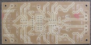
Here is a pic of the unpopulated board. It is quite simple, and is based off the schematics on Mark Hennessy's website. Thanks Mark for the inspiration. I should have a finished prototype soon. The digital side is pretty much done. We haven't done the power supply yet, and are just using a bench supply for the analog stage now.
--
Brian
Attachments
Hi Brian,
I'm impressed with your board layout, and very pleased that my site was helpful to you
You've been able to optimise the layout by freeing yourself from the mechanical constraints that I imposed on myself. I wanted to minimise the interconnections by using things like ribbon cable and PCB-mount phono sockets...
Your layout has lots of copper dedicated to earth, which is an excellent plan. One suggestion, though. I notice that there isn't a power supply decoupling capacitor at the input-end of the PCB. It might be worth trying to solder a couple on the back of the board during listening tests. It might not make any difference, but the PGA2310 datasheets made quite specific recommendations about it.
I notice that you've included gain on the input buffer. I added a very small amount of gain there to compensate for the losses in the input filter - this was only for the benefit of the fixed-level listen-source output that I provided, indeed I didn't bother for the surround-channels. So, you'd be able to simplify that end of the board if you wanted...
Out of interest, what do C15 and C25 do? I ask because they appear to be electrolytics! I guess that they are the 1nF caps that I used to set the -3dB point to 100kHz...
Very impressive work! I can't wait to see the assembled version... Which CAD package does your roommate use?
dwk123: If you are able to control the individual bits of a PC parallel port, then you should have no problem controlling these chips. You just need 3 lines for clock, data and latch (or strobe). You could also control the mute input with another bit - I mute via software. The timing diagrams in the datasheet should tell you everything, but feel free to ask for more info...
mhennessy said:I'm impressed with your board layout, and very pleased that my site was helpful to you
You've been able to optimise the layout by freeing yourself from the mechanical constraints that I imposed on myself. I wanted to minimise the interconnections by using things like ribbon cable and PCB-mount phono sockets...
Your layout has lots of copper dedicated to earth, which is an excellent plan. One suggestion, though. I notice that there isn't a power supply decoupling capacitor at the input-end of the PCB. It might be worth trying to solder a couple on the back of the board during listening tests. It might not make any difference, but the PGA2310 datasheets made quite specific recommendations about it.
I notice that you've included gain on the input buffer. I added a very small amount of gain there to compensate for the losses in the input filter - this was only for the benefit of the fixed-level listen-source output that I provided, indeed I didn't bother for the surround-channels. So, you'd be able to simplify that end of the board if you wanted...
Out of interest, what do C15 and C25 do? I ask because they appear to be electrolytics! I guess that they are the 1nF caps that I used to set the -3dB point to 100kHz...
Very impressive work! I can't wait to see the assembled version... Which CAD package does your roommate use?
This is my roommate second pcb layout that he has made. He messed up on the first try with this board. I showed him how to use the ground plane in Protel, so that is what he is using. He is using Protel DXP now. I will ask him about the purpose of those caps.
Thanks again. I will get more pictures up after Thanksgiving.
--
Brian
Well, here is the picture of the assembled board. Notice the reversal of the +/- vcc for the opamps...
Mark,
The caps you were referring to are not electrolytics, he just set the footprint wrong. He will fix it in the next revision. The circuit is straight from your schematics on your website.
Picture at:
http://brian.darg.net/album11/aag
click the image for a hirez version.
I should have shown the bottom, there is a single row of pins sticking out that allow you to stack the board into another. It should work well for a scalable pre-amp.
--
Brian
mhennessy said:Hi Brian,
dwk123: If you are able to control the individual bits of a PC parallel port, then you should have no problem controlling these chips. You just need 3 lines for clock, data and latch (or strobe). You could also control the mute input with another bit - I mute via software. The timing diagrams in the datasheet should tell you everything, but feel free to ask for more info...
Thanks. I reread the datasheet last night, and I can't see anything that would cause a problem. The signal levels should be fine, and the timing is so flexible on these chips that almost anything should be able to drive them.
I'm running Linux, so low-level port control shouldn't be a problem. Looks like it's time to forumlate a plan.
A suggestion: plan for optoisolators to break any possible ground problems. I'm sure you could clock the bits slow enough so that any old devices would work, but it could save you a lot of grief.dwk123 said:
Thanks. I reread the datasheet last night, and I can't see anything that would cause a problem. The signal levels should be fine, and the timing is so flexible on these chips that almost anything should be able to drive them.
You may also want to fuse the lines to avoid damage to your expensive PC if you have a wiring error. Seen it happen...
Hi Brian,
Still impressed with your PCB! Question: what are the resistors you've used? They look expensive
And, how do you think it sounds?
Something else to try - C15 and C25 (the 1nF caps). I notice you've used ceramic caps here - it might be worth trying something better. Let us know if you hear a difference. I used a plastic cap (can't remember the type).
You could also try losing the small ceramics on the input and output. I put them there to protect against ultrasonic noise, but I'd be interested to know if you hear a difference without them (or if they sound better for being non-ceramic)
Unfortunately, I haven't got the time to try these tweaks for myself at the moment Maybe during the Christmas holidays...
I like the stacking idea. Just one question - how are you going to cascade the shift registers in the PGA2310's? If you look at my diagrams, you'll see that I took the data-out from the first PGA2310 and connected it to data-in of the next. This means that I have to send a 6-byte word when changing volume, but it means that I can address them individually. It appears that you are planning to simply parallel-connect them all, and this might work ok (just watch data-out pins), but you have to send the same data to all of them at once. Obviously this is only an issue if you scale up for 6-channel, as you might want to control them individually...
And dwk123 - optocouplers are an excellent plan Forgot to suggest it myself... Should only need 3 for a basic implementation... Good luck with your experiments - let us know how you get on!
Still impressed with your PCB! Question: what are the resistors you've used? They look expensive
And, how do you think it sounds?
Something else to try - C15 and C25 (the 1nF caps). I notice you've used ceramic caps here - it might be worth trying something better. Let us know if you hear a difference. I used a plastic cap (can't remember the type).
You could also try losing the small ceramics on the input and output. I put them there to protect against ultrasonic noise, but I'd be interested to know if you hear a difference without them (or if they sound better for being non-ceramic)
Unfortunately, I haven't got the time to try these tweaks for myself at the moment
Maybe during the Christmas holidays...I like the stacking idea. Just one question - how are you going to cascade the shift registers in the PGA2310's? If you look at my diagrams, you'll see that I took the data-out from the first PGA2310 and connected it to data-in of the next. This means that I have to send a 6-byte word when changing volume, but it means that I can address them individually. It appears that you are planning to simply parallel-connect them all, and this might work ok (just watch data-out pins), but you have to send the same data to all of them at once. Obviously this is only an issue if you scale up for 6-channel, as you might want to control them individually...
And dwk123 - optocouplers are an excellent plan
Forgot to suggest it myself... Should only need 3 for a basic implementation... Good luck with your experiments - let us know how you get on!I have looked this one up-
The disadvantage is that TI assures us that the voume regulation is done thru a standard Op-amp, and I wouldn't want one more of these.
A competitor is the analoge devices 8400-8402 8404,which insofar as the company reports, is a straight potentiometer output. The control interface, serial data, is more or less the same. I would be happy if you provded more info on this kind of circuitry, as I don't understand anythihg about this level of digital.
It looks like you have used a copper pour for the ground plane. There are advantages and disadvantages to this. From a purely simple noise standpoint, an all-over ground plane is great. However, for the absolute best in analog performance, a poured ground plane is actually not the best way to go. By using a poured ground plane, you have lost all control over where your ground currents are flowing. Even though it is a lot of copper, when you are talking 96db of dynamic range or more, a small difference in ground potential from one side of the board to the other can make a huge difference. Star-Grounds, often applied when wiring, are just as applicable in PCB design.
Alvaius
Alvaius
- Status
- This old topic is closed. If you want to reopen this topic, contact a moderator using the "Report Post" button.
- Home
- Amplifiers
- Solid State
- Volume control