Hi, ive a working mic preamp however im wanting to alter the tone of the output by adjusting trebel and bass. I understand the principal behind the common 741 active trebel and bass circuits such as shown here http://www.antonine-education.co.uk/Electronics_AS/Electronics_Mod2/topic_2_8/active_filters.htm
However is it possible to combine a trebel boost and bass boost filter on one output and swap the resistor value in each for a log potentiometer to vary the amount of trebel and bass, in essence to form a basic tone control?
If so, linking the circuity in parallel should work?
Thanks for any help
However is it possible to combine a trebel boost and bass boost filter on one output and swap the resistor value in each for a log potentiometer to vary the amount of trebel and bass, in essence to form a basic tone control?
If so, linking the circuity in parallel should work?
Thanks for any help
") /sreten.
/sreten.hi thanks, the active versions look rather ideal, but for now im wanting something much simpler. Basically i want to link a high pass and low pass simple active filters and add relplace a resistor with a pot to allow me to alter the bass and trebel individually.
This should be possible?
Thanks
This should be possible?
Thanks
DD_Davo said:Hi, ive a working mic preamp however im wanting to alter the tone of the output by adjusting trebel and bass. I understand the principal behind the common 741 active trebel and bass circuits such as shown here http://www.antonine-education.co.uk/Electronics_AS/Electronics_Mod2/topic_2_8/active_filters.htm
However is it possible to combine a trebel boost and bass boost filter on one output and swap the resistor value in each for a log potentiometer to vary the amount of trebel and bass, in essence to form a basic tone control?
Yes, but why would you want to?
DD_Davo said:If so, linking the circuity in parallel should work?
You'd need another op-amp to make a linear adder, otherwise, you might run into a race situation where the output transistors of the op-amps try to short out the DC rails. Not a good thing.
Why not use This instead? Straight from an elementary text on op-amps: uses but one op-amp (do replace the suggested op-amp with a really good one) provides both bass and treble cut/boost, and is a helluvalot simpler and easier to implement.
right thanks everybody im testing out all the varying options. One question though, take a standard bass boost active filter using a 741, 2.2K, 2.2M, 10K and 47Nf capacitor. It works fine, in that it boosts the bass frequencys a little however something is not quite right as powering the opamp makes no difference, therefore it seems to be working passively. Im using 9V pp3 batteries but i should have thought them to work fine?
Thanks
Thanks
What frequencies are you hoping to boost? The values you've used will work fine for bass in the 'music' sense - i.e. drums, synth, bass guitar etc. But, if you're talking about voice (or electric guitar), the effect of the boost will be much more subtle. Perhaps this is what's happening...
Cheers
Cheers
ok heres the image. I have labelled the power rails im using and where the audio input and output feeds are in blue (input to the filter) and green (output from filter) The little green and blue blobs show where ive connected the grounds of the input/output of the audio feed.
Attachments
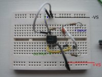
You've connected pin 3 and pin 4 together.
-Vs is NOT the same as ground!!
This is a bit hard for beginners (I certainly made the same mistake).
Try this:
+ --------- +Vs
9V bat
-
|------ gnd
+
9V bat
- -------- -Vs
pin 4 of opamp is the only connection to -Vs
pin 7 of the opamp is the only connection to +Vs
gnd - where all grounds go.
Cheers
I see an easier mod to follow to get things right. See the wire that connects to pin4 of the 741? Its currently connected to the 2nd row of holes at the top of the proto-board.
MOVE that wire so its in the FIRST row of holes of the proto-board. And, connect that row to -Vs.
Cheers!
ps: you may want to plug a spare 741 after this mod, as the current one may have died...
MOVE that wire so its in the FIRST row of holes of the proto-board. And, connect that row to -Vs.
Cheers!
ps: you may want to plug a spare 741 after this mod, as the current one may have died...
Hi,
once you have the circuit working, pull out the 741 and turn it around with the dimple at the wrong end. Plug it back in and power up.
Now pull it out turn it so the dimple is the correct way again and plug it back in.
Tell us after this is done whether it still works.
The 741 is one of the most robust opamps ever designed.
- Status
- This old topic is closed. If you want to reopen this topic, contact a moderator using the "Report Post" button.
- Home
- Amplifiers
- Solid State
- preamp active filters