Good point Upupas") .
.
I will also provide for extra mounting-holes for c1 and c2, so you can toy around with C's.
Right now i'm using panasonic 1500 uF low-esr types just for fun. It is amazing what you can get away with in this amp if you run separate filter-ground.In my previous monster i noticed degrading of sound even going from 100nF to say 10uF....
with kind regards,
Klaas
.I will also provide for extra mounting-holes for c1 and c2, so you can toy around with C's.
Right now i'm using panasonic 1500 uF low-esr types just for fun. It is amazing what you can get away with in this amp if you run separate filter-ground.In my previous monster i noticed degrading of sound even going from 100nF to say 10uF....
with kind regards,
Klaas
Another suggestion on the PS decoupling
Snubberize it...
Having read many the posts and discussions on the Gainclone I hesistate to mention it.
I have indeed also observed that the specific choice of the capacitor type and value in decoupling is critical. e.g. 15 nF polyprop ersus 6.8 microF solid tantal is different.
Now having heard of snubbers this would requires a separate island to connect a resistor to a capacitor.
I have capacitors with built-in resistor (470 ohm + 100 nF MKT) - a type intended for supplies.
albert
And another suggestion.
This is related to the follow-up work designed by Hiraga of the L'Audiophile team on the Hybrid amplifier 'Pacific'.
see this: http://www.bonavolta.ch/hobby/en/audio/pacific.htm
The input differential of course has some distortion, and both legs can differ a little bit in harmonics. Hiraga suggested to make the 82k/2k voltage divider variable just to be able to change the harmonics structure a little bit. You should be able to see the result for each leg separately, I expect, in open loop measurements.
Of course this might be a crazy idea in the context of LeMonstre. The two halves of the circuit are different. And can hardly be measured independently. Nevertheless - it could be a new solution to a non-existing problem.
albert
This is related to the follow-up work designed by Hiraga of the L'Audiophile team on the Hybrid amplifier 'Pacific'.
see this: http://www.bonavolta.ch/hobby/en/audio/pacific.htm
The input differential of course has some distortion, and both legs can differ a little bit in harmonics. Hiraga suggested to make the 82k/2k voltage divider variable just to be able to change the harmonics structure a little bit. You should be able to see the result for each leg separately, I expect, in open loop measurements.
Of course this might be a crazy idea
in the context of LeMonstre. The two halves of the circuit are different. And can hardly be measured independently. Nevertheless - it could be a new solution to a non-existing problem. albert
Albert, about the snubberizing i can only speak from experience with gainclone.I built original gainclone from Paul's original SE-kit.
On my speakers (4 ohms at lf) low-end sounded too slow for my likings BUT detailed.thats why i like amps like krell or bryston: low end sounds like amp is able to throw woofer-cone in your lap .
Adding capacity firmed up low-end a lot, but no matter what i tried in ps-setup, magical midrange was gone.Sometimes i got pretty close but not close enough for me.Snubberizing didnt do anything for me-well at least not a lot.In my opinion Paul's GC is 'balanced to-the-max' as is (Kudos for that Paul), i just like another taste of candy.
with kind regards,
Klaas
On my speakers (4 ohms at lf) low-end sounded too slow for my likings BUT detailed.thats why i like amps like krell or bryston: low end sounds like amp is able to throw woofer-cone in your lap
.Adding capacity firmed up low-end a lot, but no matter what i tried in ps-setup, magical midrange was gone.Sometimes i got pretty close but not close enough for me.Snubberizing didnt do anything for me-well at least not a lot.In my opinion Paul's GC is 'balanced to-the-max' as is (Kudos for that Paul), i just like another taste of candy.
with kind regards,
Klaas
Upupa Epops said:" L' Audiophile team " don't know correctly connect volume pot...
Agree, there is a nice simulation on a Danish site on the effect of a volume pot 'as a low pass filter', with these values the system might not get more that 40kHz bandwidth :-(
Now onto the PCB:
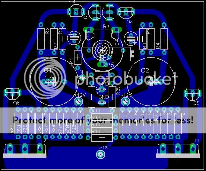
added horizontal multiturn-pot. on vertical multiturn spacing between legs is too small to use trick of running pcb-track under pot.People with shaky hands who are afraid of shorting legs of r9/r8-r4 while adjusting pot, there's a tool for that: plastic adjuster .
Didnt add mountingholes yet, t2 is difficult:dont want to change conn. between t2/t1.if everyone used plastic standoffs it would be easy.Let me know what you think
With kind regards,
Klaas
added horizontal multiturn-pot. on vertical multiturn spacing between legs is too small to use trick of running pcb-track under pot.People with shaky hands who are afraid of shorting legs of r9/r8-r4 while adjusting pot, there's a tool for that: plastic adjuster
.Didnt add mountingholes yet, t2 is difficult:dont want to change conn. between t2/t1.if everyone used plastic standoffs it would be easy.Let me know what you think
With kind regards,
Klaas
In my experience using passive pot as "pre-amp" is like audio-lottery, unless you know in your setup what is ALWAYS in front and after pot (source-cables-(pot)-cables-power-amp).
i like a little more consistency when changing equipment... just my opinion.
With kind regards,
Klaas
i like a little more consistency when changing equipment... just my opinion.
With kind regards,
Klaas
Upupa Epops said:Basic mistake of original schematic is too high gain - 23 * is for this output power unnecessary... ...
Upupa and specifically Forr: having critics on the schema. This led me to think out the following regarding the the output stage.
What would happen if a small (say 1 mA) current source would be dumped into the collectors of the driver transistors, from the opposite rail? The driver would have more breathing space. Now the current could be really reduced to a low value, making the amplification factor maybe dependent on the current. The added power is about 15 milliwatt per milliamp. Suggestion: A FET 3 mA current source ( a 2SK30) or a 5k resistor.
This looks like what Hiraga did in his 20 Watt output stage. He used 1k8.
(what is your opinion)
albert
Justcallmedad said:I would tie a resistor between the 2 collectors for better linearity and a more constant power on the drivers...
Dad - Great idea, however the collectors are just 1.2 volt apart.
Is then a resistor of say 1 kOhm be OK? Or a current source could do (single 2SK30) having a 3 mA drain.
Upupa - would two 1 kOhm resistors do? Would be like reinventing the darlintonnot. (I got myself in some knot here!)
Sorry, Klaas, my questions looks like hijack.
albert
Sorry, Klaas, my questions looks like hijack
Dont worry about it Albert.
I dont consider it to be my thread, i just started it.If nobody responded it wouldnt be a thread
.The main reason i dont mingle in the discussion to change the topology is, that my knowledge of analogue electronics is limited.
So if i dont have anything constructive to add i think it is wise not to react. This doesnt mean i'm not curious about worthwhile changes, i'm just carefull with implementing them.
I consider my main input here to design pcb and learn along the way.In other words: keep the suggestions coming, but pls dont expect me to understand everything you are talking about.
pcb now is like this:
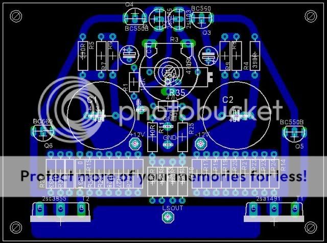
I'm also working on pcb for old parts
(still in draft stage though)Justcallmedad, i'm still using 2sk246/2sj103.those zetex-devices are better ?
With kind regards,
Klaas
Justcallmedad said:I will go for something between 100R to 300R (5 to 15 mA, even more) depend on your driver choice, these devices are very critical...
Are still your input fets SK246/SJ103?
yes I have the original drivers (2SB7l6/2SD756 ). Maybe next weekend I'll start off with a small current added. Just a little bit of Class A from the oposite rail. 3 k probably. I am a little bit worried to have the two halves of the amplifier interacting on the driver side. Adding the rsistors should lower the main current on the output, if I'm right.
I'm always afraid of FIRE. I've also learned that you shoiuld touch something that is working correctly.
On the input I have the 2SJ74 and 2SK170.
It's a remarkable lot.
albert
japanese amp design
Dear members
Maybe some of you can give me a comment to this design I have found in the web.http://www.geocities.jp/mutsu562000/root/amps1/htm/e/indexe.htm.
What do you think about that schematic?
Can sombody give me his opinion about this circuit?
Thank you for your help.
P.S. Ididn't want to start a new threat for this
Attachments
- Status
- This old topic is closed. If you want to reopen this topic, contact a moderator using the "Report Post" button.
- Home
- Amplifiers
- Solid State
- le monstre questions