There are analog optocouplers but the quality isn't enough for audio I'm afraid. Check for instance IL300 from Vishay. I have used it in a 4-20mA loop and for this purpose it's OK.
http://www.vishay.com/optocouplers/list/product-83622/
http://www.vishay.com/optocouplers/list/product-83622/
There are some instrumentation isolators that may be good enough for audio, using a pwm system across capacitors.
Linear modulation of an IR diode driving a PIN diode works fairly well except at very low frequencies where I have seen strange non linearity and memory effects.
A transformer may be your best solution.
Linear modulation of an IR diode driving a PIN diode works fairly well except at very low frequencies where I have seen strange non linearity and memory effects.
A transformer may be your best solution.
Hi, thanks for these great reply.Not built anything yet.It's for my 4way active crossover project.When I hook it up to a power amplifier, I got some hum in the speaker.Tried some tricks like disconnect ground from one end of interconnect but this is the worse I can do, more hum.tried some other interconnect with same result.
Just take a look at this link, this is my crossover project.Every cables is sheilded, separate transformer, each board has it's own filtering caps and voltage regulator. All capacitors are polystyrene or polypropylene for the bass output. all ICs are NE5532.Each ICs has a 22 Ohm resistor and a 22uF capacitor at the neg and positive input. Just let me know what you think. Thanks
http://img98.imageshack.us/img98/1875/mycrossover17pl.jpg
http://img117.imageshack.us/img117/8842/mycrossover20de.jpg
http://img95.imageshack.us/img95/5659/hautparleur18eh.jpg
The last pic is a picture of my 4way speaker that I've built.
All my power amp are Rotel exept for the 15 inches drivers this are power by an Harman Kardon citation 7.1 with 450 watts/channel.
My crossover is built in a Rotel power amplifier case that has been modified, reduce in height to match the height of my Rotel line conditionner.Still have to finish the front(sanding and painting to match other Rotel components.
Here is my design for the 4way crossover, should sound great if everything is O.K.
http://img92.imageshack.us/img92/103/4waycrossover114ai.jpg
http://img92.imageshack.us/img92/103/4waycrossover114ai.jpg
HI, thanks for those great reply. What could I do, replace every every connectors.I don't know if I can isolate them from the case, I think I can't.Here's the pic of the RCA connectors I use.
http://img55.imageshack.us/img55/4926/rcaconnector2ay.jpg
What is the main reason why those connectors should not be grounded to the case, they will be anyway with the sheild.
Thanks
http://img55.imageshack.us/img55/4926/rcaconnector2ay.jpg
What is the main reason why those connectors should not be grounded to the case, they will be anyway with the sheild.
Thanks
You should only have one ground, and that should be of star formation feeding off to everything that needs a ground. By allowing the sockets to contact the chassis you make multiple ground points which can create eddy currents in the chassis (if steel) but also slightly different ground paths will be present.
Hi "Ostie01" (it sounds weird a little bit knowing what it means...)
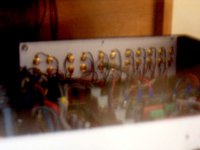
I agree with Richie00boy. Your RCA input/output jacks should be isolated. You can use the same non-isolated jacks if you do not want to buy new isolated ones. Just increase the size of the holes in the metal chassis so they do touch the RCA jacks at all. Then use an isolating material like plexiglass plate (for example) and fix all RCA jacks to it. Afterwards, just fix your plexiglass plate witch screws to the rear metal chassis. See example in attached picture (sorry for the picture quality...)
Good luck
Attachments
Hi, well this not seem to work , nothing changed, same hum.Just remove rca connectors from case , put some electrical tape around to prevent short circuit and still have that hum.
Here's a pic at output of speaker B , sorry for poor quality pic but it's not easy to take picture of a screen.
http://img86.imageshack.us/img86/1015/oscillo5yv.jpg
Here's a pic at output of speaker B , sorry for poor quality pic but it's not easy to take picture of a screen.
http://img86.imageshack.us/img86/1015/oscillo5yv.jpg
HI, not sure of what you are talking about.Do I have to isolate the two main boards from the case, i.e. there's a ground path that's surround the two boards and the the screws that support the boards are made with metal and touches the ground path around the boards and are screwed to the metal case.Here's another pic with some comments, maybe this can give you a better idea.
http://img90.imageshack.us/img90/9259/mycrossover11im.jpg
http://img90.imageshack.us/img90/9259/mycrossover11im.jpg
Hmm that doesn't sound ideal.
Your central ground should be at the centre of your PSU capacitors, then anywhere that needs a ground should have it's own wire from this point. There should be no other paths. This prevents any ground loop currents from forming within the subsystem, but also ensures that one board or whatever putting a lot more current into/out of ground does not influence the other boards grounds.
I think you have some reading up on good grounding principles to do before you attempt any more of this project. Your main issue could be caused by something else, but it is important IMO to get your basics right.
- Status
- This old topic is closed. If you want to reopen this topic, contact a moderator using the "Report Post" button.
- Home
- Amplifiers
- Solid State
- optocoupler to eliminate ground loop