Hi.
I've got 24 MJ15003 and was wondering if its possible to make a class AB with only those N-channels in the output-stage.
I seem to remember an old Elector Electronics schematic with approx 40W/8 Ohms that used 2n3055 in the output-stage. The Output was made up with two "super-transistors" each build with a 2N3055, a few other transistors and a handfull of resitors.
I actually build one of those and it worked very fine.
I'm noy looking for super-hifi, but a decent qual.
TroelsM
Yes, it is possible to produce output stages with NPN power devices and it was extensively done before 1980s, until suitable PNP power transistors become affordable.
You should ask for "quasi-complimentary" output stages instead, as N-channel refers almost exclusively to MOSFETs.
You should ask for "quasi-complimentary" output stages instead, as N-channel refers almost exclusively to MOSFETs.
lindseyhood got a credible 0.01% with his 75 watt design and npn output devices this is still a credible circuit allthough not to complex i would start there theres also the quad 303
and even a 405 all npn devices
or go the whole hog and build a npn armstong 521 all the devices would be npn now there is a challenge rather a lot of capacitors though !
regards trev
and even a 405 all npn devices
or go the whole hog and build a npn armstong 521 all the devices would be npn now there is a challenge rather a lot of capacitors though !
regards trev
")
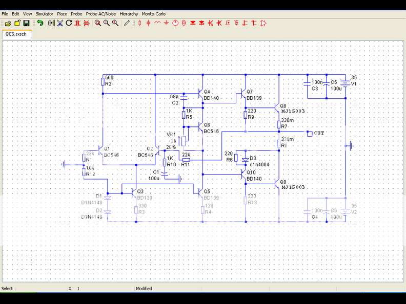
Take this as an example
P3a
Connect the collector of Q5 and Q7 (your NPN device) directly to the V+ rail, Connect the emmiter of Q5- base of Q7 with R11 going from output to emmiter of Q5 (base of Q7) and the emmiter of Q7 to output. Leave Q6 and Q8 in the same configuration, however instead of the E of Q6 going directly to C of Q8, put a 1N4004 diode in series with the E of Q6 (paralell the diode with a 220 ohm resistor).
After that modification you will want to track the temperature of the OPTs instead of the drivers, so mount Q9 directly to the heatsink. This I'm sure will give you more than satisfactory results.
Hi,
At the request of another member (Zeonrider) I posted a schematic of my N-channel mosfet amp modified for bi-polar outputs. If you are patient I will build the prototype over the next 2 months or so. The schematic is shown here. http://www.diyaudio.com/forums/showthread.php?postid=822751#post822751
As a guide the design is intended for +/- 75 volt rails and 8 output transistors per board. This will deliver around 220 watts into 8 ohms and around 380 wats into 4 ohms.
Cheers
This is something I designed to run a subwoofer. It sounded very nice on full range speakers also. It was intended for a sealed enclosure so hence the lack of VI limiting. If you want something simple, this should be more than adequate. Note that Q3 could be replaced with a BC546 if you wish.
- Status
- This old topic is closed. If you want to reopen this topic, contact a moderator using the "Report Post" button.
- Home
- Amplifiers
- Solid State
- N-Channel with bipolars?