hey, i set the pot to maximum and monitored everything on power up.. it worked.. but same problem as before. i tried pluggint he mini disc player straight into the SS section and got pretty good quality sound out very quiet.. qith the tube section it sounds good at very low volumes and then as you turn the input level up it isnt happy...
Owen
Owen
I know Chris is a fan of the CCS approach, but I would vote for the bootstrap approach first, then refine it further (if needed) with CCS.
The relatively low value resistors from input to rails make the job of your tube front end VERY difficult (it sees an impedance of about 5k, and it would be much happyer with at least 10 times that, or even 100 times).
You may want to just increase them like I mentioned in my reply above re bootstrapping, even without the actual bootstrap caps, it should make it possible to drive the SS stage to a slightly higher volume. If that turns out to be the case, then you are on the right track.
In theory, you could increase these resistors quite a bit but then you would have problems with redesigning the bias generator for that, so I think a bootstrap test would be a better idea than making the resistors too large.
i have tried the resistor version useing the 2 x 12K resistors + and - with and without the bootstrap caps.. i used an output cap to get rid of the DC offset for testing purposes.. it was about twice as loud with the bootstrap caps in place.. I havent tried the CCS version yet though..
Many Thanks,
Owen
Many Thanks,
Owen
just played a lil more. measured about 4V DC offset!!! and it went up to about 6V with volume at max!! dosnt sound right to me but im gunna wait and see what you guy's think..
Owen
Oh dear.. It's got to the point where ive had to bake more flapjacks and put my thinking hat on Flapjacks are brain food
Owen
Owen
Oh dear.. It's got to the point where ive had to bake more flapjacks and put my thinking hat on
Flapjacks are brain food Owen
Attachments

Hi ilimzn,
In this case, a CCS solved some problems for me in one easy to implement fashion. The LED's are pretty too. I'm always open to suggestions.
Anyway, I was looking for about 100K (my ground reference) and the CCS didn't load this down much further.
Owen,
How have you referenced your input to ground?
-Chris
i have it bootstrapped at the moment, i took the bootstrap cap's out and the volume decreased and distortion increased so i have put them back in... what resistance should i put accross the input on the SS stage? i tried it with a 470K and there was no differance that i could tell....
Owen
Owen
ive no idea what the input impedance is but i think your right about it being too low, I'm not 100% on how the bootstraping affects the input impedance.
I cant actually remember if i got those transistors, i'll have to have a look... I have a lot of transistors...
This is what the schematic looks like at the moment...
I cant actually remember if i got those transistors, i'll have to have a look... I have a lot of transistors...
This is what the schematic looks like at the moment...
Attachments
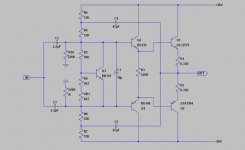
Time for some voltage measurements!
Remove the two 220k to ground from SS stage inputs (after caps as in your schematic). Disconnect the input completely, also connect some sort of high impedance load (like a 1k resistor) directly from output to ground (not through a capacitor). Then with the negative end of the voltmeter strapped to ground, measure the following:
0) Power rail voltages
1) Voltage at base of Q2 and Q4
2) Voltage at base of Q1 and Q5
3) Output voltage
4) Voltage at junction of R4 and R6
5) Voltage at juntion of R8 and R7
Then, also, the voltage across either one of the 0.33 ohm resistors, this we use to derive the idle current. Keep in mind that unlike the CCS approach, bootstrapping will not work right if the output stage is considerably underbiassed, and the input impedance will vary wildly (like with a 1:100 ratio) depending on input signal.
Something is fishy, the offset voltage looks far too high at 4V, with or without ground reference. Check what the offset voltage is with bootstrap caps removed as well.
Assuming you get the circuit to work properly (and I think something is not right yet), adjusting the offset voltage should easily be solved by replacing one of the 12k resistors closer to the power rails with a 10k resistor and 4.7k trimmer in series.
We need to get this stage to work on it's own under static conditions before we start connecting inputs and outputs to it
- Status
- This old topic is closed. If you want to reopen this topic, contact a moderator using the "Report Post" button.
- Home
- Amplifiers
- Solid State
- Hybrid amplifier.. Please help..