Hello,
I've build the Figure 11.4 amplifier from G. Randy Slone's High-power audio amplifier manual. I constrcuted two versions one with and one without RFI filtering capacitors. Both versions show a THD of -73dB (0.022%). The book states that 0.0009% can be "easily achieved".
I measured the THD using a Creative Audigy NX which shows -85dB THD when in loopback configuration, so that device seems to be adequate to measure.
What is wrong here? Do I measure in the wrong way? Did I make a mistake when building the amps? Or is 0.0009% not easily achieved?
Thanks in advance,
Remco Poelstra
Hi, it's possible that grounding issues mess up your measuring results.
Try a CD-player as signal source, this compensates for the worst grounding problems. Have you separated power and signal gnd ?
Can you show FFT of these distortions ? 0.022% is really not low distortive...
Mike
Try a CD-player as signal source, this compensates for the worst grounding problems. Have you separated power and signal gnd ?
Can you show FFT of these distortions ? 0.022% is really not low distortive...
Mike
Thoru said:Hello,
I've build the Figure 11.4 amplifier from G. Randy Slone's High-power audio amplifier manual. I constrcuted two versions one with and one without RFI filtering capacitors. Both versions show a THD of -73dB (0.022%). The book states that 0.0009% can be "easily achieved".
I measured the THD using a Creative Audigy NX which shows -85dB THD when in loopback configuration, so that device seems to be adequate to measure.
What is wrong here? Do I measure in the wrong way? Did I make a mistake when building the amps? Or is 0.0009% not easily achieved?
Thanks in advance,
Remco Poelstra
Hello Remco
I´ve built that design too. I've never measured it since I don't have appropriate equipment. But I was really not so worried with measuring this since it sounds really good to me.
Although Slone's designs persue really low THD measurements for 2nd and 3rd order harmonics, as we can see in his books, I don't think the THD numbers he provided were actually measured parameters. It seems to me they are simulation measurements, which most of us know that are different from real circuit measurements.
The bottomline is, your measurements may be good. Even if they are discrepant from the theoretical figure, in my opinion, they seem good for a good quality amplifier. 0.0009% is not really achivied, it requires more sophisticated circuit such as the ones he provides in the book with symetrical (mirror) diff inputs and VAS.
Anyway, you may review your measurement procedure, ensure your cables are ok, soundcard is Ok and etc.
I hope that helps,
João Pedro
Hi João Pedro, my experience is that sims are not too bad with their predictions (unless you use mosfets). In my amp sims predicted ~-85db, i measured -80db. (in my case caused by PSU artefacts) If theoretical and measured are getting that far, something is wrong with the layout,signalsource or measuring. A distortion increased by factor 22 needs research.
Mike
Mike
Experience seems to show that these books from famous authors doesn't always tell the truth. Check this thread about the same book (the first two pages): http://www.diyaudio.com/forums/showthread.php?s=&threadid=16796
Thanks fot the replies.
It indeed sounds rather well. I couldn't judge it very good because the room was very noisy. But I love figures, so I want to get that THD low")
I can try to snap some screenshots of the FFT window. Will be monday I think before I've access to the lab again.
About grounding: I've a central groundpoint where I tie all grounding to. I think people call it star grounding. The signal ground is create by a sepaerate wire which goes from the plug to the PCB. On the PCB ground is connected to PSU ground and the plug is mounted to the chassis which is grounded. From an EMC perspective this should give me the lowest transferimpedance possible. I didn't hear any 50Hz components (or multiples), so grounding doesn't seem to be a real problem, but indeed it might be that the soundcard thinks different.
Remco Poelstra
It indeed sounds rather well. I couldn't judge it very good because the room was very noisy. But I love figures, so I want to get that THD low
I can try to snap some screenshots of the FFT window. Will be monday I think before I've access to the lab again.
About grounding: I've a central groundpoint where I tie all grounding to. I think people call it star grounding. The signal ground is create by a sepaerate wire which goes from the plug to the PCB. On the PCB ground is connected to PSU ground and the plug is mounted to the chassis which is grounded. From an EMC perspective this should give me the lowest transferimpedance possible. I didn't hear any 50Hz components (or multiples), so grounding doesn't seem to be a real problem, but indeed it might be that the soundcard thinks different
.Remco Poelstra
MikeB said:Hi João Pedro, my experience is that sims are not too bad with their predictions (unless you use mosfets). In my amp sims predicted ~-85db, i measured -80db. (in my case caused by PSU artefacts) If theoretical and measured are getting that far, something is wrong with the layout,signalsource or measuring. A distortion increased by factor 22 needs research.
Mike
Hello Mike,
I've been following your posts with great interest. Yes, you are right, considering the discrepancy factor between the theoretical and actual measurements I think it is a good idea to check if there is some room for improvement or something wrong was done.
The reason I said that sims' results can be misleading was because of my (not so big) experience with strange sims results, bad models, etc which can drive you crazy sometimes. But sims are a great tool, indeed.
Thanks for pointing that.
Thoru said:Thanks fot the replies.
It indeed sounds rather well. I couldn't judge it very good because the room was very noisy. But I love figures, so I want to get that THD low
I can try to snap some screenshots of the FFT window. Will be monday I think before I've access to the lab again.
About grounding: I've a central groundpoint where I tie all grounding to. I think people call it star grounding. The signal ground is create by a sepaerate wire which goes from the plug to the PCB. On the PCB ground is connected to PSU ground and the plug is mounted to the chassis which is grounded. From an EMC perspective this should give me the lowest transferimpedance possible. I didn't hear any 50Hz components (or multiples), so grounding doesn't seem to be a real problem, but indeed it might be that the soundcard thinks different
Remco Poelstra
Another thing about this amp,
I had problems with its grounding scheme. I got it much better now but it still makes some low hum with no signal input. By analzying the circuit layout I could see that the signal ground(input and feedback capacitor) and power grounds (PSU decoupling caps, etc), share the same tracks. We know that should not be the case as we are mixing 'dirty' and 'clean' grounds. I removed the input from that track but to do the same with the feedback cap you have to modify the layout, which is more difficult.
What I am trying to say is, maybe there can be some improvements at the grounding scheme (like Mike said) so you can get better results.
Best regards,
João Pedro
Thoru said:Ok, I see.
But how should I connect it then? If I totally seperate the signal ground from the PSU ground, than the signal voltage is undefined. So they must be linked somewhere. Where should that be than?
Remco
The signal ground will be reconnected, not disconnected. I think I wasn't clear, sorry.
Here is the situation:
If you got the boards layout for this amp from SLone's book, you will notice that it only contains two ground connections (signal input and power ground) and these share the same track. According to good star ground procedures that's not a good practice, you should have separate tracks for signal/feedback (clean) ground and power/decoupling ground (dirty). Then, you run separate wires from each to the star ground. This way, you don't have PSU noise/rectification artifatcs thrown at the signal ground which can make your amp to hum.
What I've done in mine was to connect inputs grounds together and run a wire to star ground, instead of connecting them to the boards. But the feedback cap ground separation requires board modification and I decided not to do it.
MAybe your distortion problem doesn't have to do with grounding problems but if you want to try these modifications...
Here is my thread on the construction of this amp:
http://www.diyaudio.com/forums/showthread.php?s=&threadid=56607&highlight=
Thanks for the explanation. I'll try it. I don't mind changing the PCB, I allready did that . I'll have to think how to place the wiring then, in order te keep the enclosed flux to a minimum.
I'll let you know the results. Will take a few days (after monday) to do the modification and the measurement.
Remco Poelstra
. I'll have to think how to place the wiring then, in order te keep the enclosed flux to a minimum.I'll let you know the results. Will take a few days (after monday) to do the modification and the measurement.
Remco Poelstra
Took a little while, but I've made some screenshots and modification.
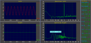
The first image shows to soundcard in loopback mode.
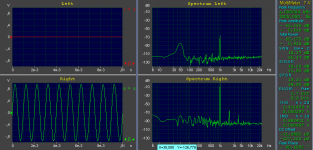
The second shows the amplifier in unmodified configuration
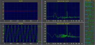
The third image shows the amplifier with the grounding modification.
In the last case the THD is actually higher than in the unmodified case.
Any comments on this?
Thanks in advance,
Remco Poelstra
The first image shows to soundcard in loopback mode.
The second shows the amplifier in unmodified configuration
The third image shows the amplifier with the grounding modification.
In the last case the THD is actually higher than in the unmodified case.
Any comments on this?
Thanks in advance,
Remco Poelstra
An externally hosted image should be here but it was not working when we last tested it.
An externally hosted image should be here but it was not working when we last tested it.
An externally hosted image should be here but it was not working when we last tested it.
Attachments
Hi Remco, 0.06% at 1khz is a bit much, you're right. The harmonic spreads looks like a problem with PSRR/supply lines and is likely to increase with 6db/Oct. This would give ~1% at 16khz which is of course way too much for a nfb design. The absence of 3rd harmonic shows that the amplifier itself works, it's likely that your problems are caused by layout or missing caps or very weak power supply. It will not sound really bad, but lack details and accuracy.
Have you tried measuring higher freqs, 4khz for example ?
Mike
Have you tried measuring higher freqs, 4khz for example ?
Mike
Thanks for your reply.
No, I only meaured 1kHz. I'll try higher frequencies after the weekend. Why do you think it increases with 6dB/oct?
The only caps I removed from the schematic are the input coupling capacitors. These I replaced with an input LP filter. And I added capacitors accros the differential input pair and a LP filter in the feedback. This way I reduced the RFI. So the amp ended up with more capacitors.
The power supply is overdimensioned for feeding two channels, so it should have no problems doing this test. It's a passive design (torodial trafo+rectifier+caps). The layout is indeed a problem, because noise from the output is coupled back to the input, but how is that exactly a probem for the THD specification?
Remco
No, I only meaured 1kHz. I'll try higher frequencies after the weekend. Why do you think it increases with 6dB/oct?
The only caps I removed from the schematic are the input coupling capacitors. These I replaced with an input LP filter. And I added capacitors accros the differential input pair and a LP filter in the feedback. This way I reduced the RFI. So the amp ended up with more capacitors
.The power supply is overdimensioned for feeding two channels, so it should have no problems doing this test. It's a passive design (torodial trafo+rectifier+caps). The layout is indeed a problem, because noise from the output is coupled back to the input, but how is that exactly a probem for the THD specification?
Remco
These distortions are typically caused by the problem that only half wave currents are flowing in the power supply lines. They go away if the amp is biased into ClassA. The half waves get induced by capacitive or inductive coupling into somewhere else.
Is the frontend somehow isolated by a resistor and caps in the supply lines ?
These half waves consist of large amount of even harmonics...
Mike
Is the frontend somehow isolated by a resistor and caps in the supply lines ?
These half waves consist of large amount of even harmonics...
Mike
The old schematic and layout are the original Slone designs.
I've attached the new schematic. I used the original layout on which I creatively added some components.
I did measurements at 2, 4 and 8 kHz. The increase in THD is 3 dB/oct.
On the higher frequencies there is a more visible 3rd harmonic component.
Mike, what do you mean with "Is the frontend somehow isolated by a resistor and caps in the supply lines ?". Perhaps you can find the answer in the schematic?
I really like to get this distortion problem fixed.
Remco
Attachments
- Status
- This old topic is closed. If you want to reopen this topic, contact a moderator using the "Report Post" button.
- Home
- Amplifiers
- Solid State
- "High" THD in Slone Figure 11.4 amp