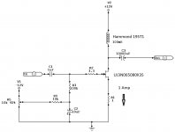
In reply to OP - I can't help with a SE amp - but here is my balanced amp, choke loaded. The circuit was originally inspired by the Hi Fi World circuit referenced above (Andy Grove/ Chris Found) but I didn't work out the output stage until i read the Wireless article in 1999 - I copied this stage outright, including using a power toroid as an output choke. In the end it was simpler to make the input stage balanced, since the out put is balanced, but I've used the same feeback to source (Current feedback?) as used by Andy Grove.
http://www.diyaudio.com/forums/solid-state/212424-balanced-class-fet-amplifier.html
Here's a SE design:
http://www.amplimos.itimages2SK180_0.gif
Of course it involves current sources but perhaps someone could suggest appropriate values for inductor that could replace them ? classAchap perhaps ?
I haven't got the slightest clue about the performance of this circuit but there's quite a collection at the originating site and most are by reputable designers.
Attachments
Here's two more links:
A circlotron:
http://www.turneraudio.com.au/solidstateamps4-50w-mono-mosfet_files/schem-50w-mosfet-classAmono.gif
and 50W pp class-A transformer output:
http://www.turneraudio.com.au/solid...-tube-mosfet-hybrid-circlotron-april-2012.gif
Both are from turneraudio.com.au and have extensive descriptions and explanation on the site. The 50W class A schematic is too confusing the way it's drawn and I had to redraw it to get my head around it - eyesight doesn't help... (I can post it if anyone else is having the same problem - caveat emptor applies of course!) I also fear it has an error in the way the differential amp. stage is drawn ?
It`s a BJT output but you could make it with mosfet with few resistor value modifications:
http://www.diyaudio.com/forums/solid-state/226296-thetwelve-se-class-tmc-amplifier.html
http://www.diyaudio.com/forums/solid-state/226296-thetwelve-se-class-tmc-amplifier.html
Covert Bifurcated Horns.
You can check out my bifurcated horns here Stelios: http://www.diyaudio.com/forums/multi-way/234576-covert-bifurcated-horns.html
And good luck with your amplifier build.
Which ones (horns) if I may ask ?
An active horn system (or even non-horn system) with 3 pairs of this amp. would be quite something! would it not?
You can check out my bifurcated horns here Stelios: http://www.diyaudio.com/forums/multi-way/234576-covert-bifurcated-horns.html
And good luck with your amplifier build.
I stumbled across a SOWTER transformer for the andy Grove circuit. "Inductance 150 mH. DC resistance 0.75 Ohms. Primary dc standing current 2.0 A max."Found it, the Andy Grove design was in HiFi World February 1996 with an alternative by Chris Found, with better linearity. Both were specified at 15W with a BUZ346 output device. There was a follow up in June 1996 in the letters page clarifying a few typos, which I have a copy of.
Not cheap but interesting (bifilar wound...)