Regulator
Viktor,
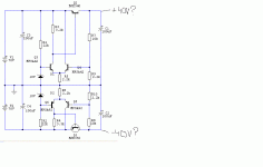
Your Q2, MJE340 is backwards. Try flipping the Collector and Emitter. This should keep either of the MPSA42s from blowing.
How much current are you passing? If it is more than a few hundred mA, then you should consider using a switching regulator, as your conduction losses would be considerably less and efficiency would go way up, keeping things much cooler.
A common buck regulator can be used for the (+) rail, and a variation of the boost (flyback) regulator can be used for the (-) rail. Heck, they can even be synchronized to eliminate any beat frequencies that would be generated!
Hope this helps!
Cheers,
Steve
The circuit is likely to work fine with real components, but you should check for frequency stability. In case of oscillation, a small miller capacitor in each output device may solve it. If part count is not critical, I would include some basic overload protection achieved with two current sense resistors in series with the emitters of the output devices and two transistors to clamp the base drive in case of overcurrent, when the voltage drop across the said resistors goes above one diode drop.
Hi,
I would look for heatsinks on the pass devices (Q1 & Q2).
is your load continuous constant current on each rail? If not then what is the real maximum current on each rail. Allow a percentage above this and then calculate your power dissipation with maximum voltage on the supply.
You have a 30V loss across the pass device. Have you thought about using your input caps as low pass filters? Add a power resistor, 2W or 3W wirewound would be perfect as a voltage dropper.
680r would drop 13.6V at your 20mA load and if C3&4=1mF//100nF give 680mS RC timeconstant to kill the majority of high frequency rubbish coming from the previous supply. It would also provide a modicum of overload/short circuit protection.
The ground sensing leads are shown in the sym and schematic as common with the main ground current return. The ground for Z, R5 & R9 should have a separate track to the output node and same for negative.
A simple constant current for Z would improve performance but constant voltage is maybe not that important to your circuit.
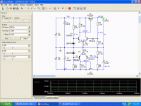
If that's the output you're getting you can bet that there's a mistake in how you wired up your (physical) circuit. Take your DVM and start measuring voltages against the voltages printed in the simulation of Circuitmaker, to find the problem.
After you've corrected the problem the output voltage will be much closer to your target +-40V. If you're still not happy with it, you can modify (R7 and R8) OR (R9 and R10), pick a pair.
After you've corrected the problem the output voltage will be much closer to your target +-40V. If you're still not happy with it, you can modify (R7 and R8) OR (R9 and R10), pick a pair.
Hi,
R3 & R4 are wrong.
R5 allows 9.1/2200 = 4.1mA through the LTP tail.
For balance across the the LTP, the current in R3 should be 50% less a correction for the current coming from the base of Q2 (20mA/50 = 0.4mA) giving Ir3=4.1/2-0.4=1.65mA
R3=0.7/1.65=430R.
I would also reduce R1 & R2 to allow 10% dissipation in the zeners, but this is not causing the problem of overvoltage.
I have build same discrete regulator circuits.
To avoid oscillation you should use compensation cap.
This is no different from an audio (OP-)amplifier with high gain and feedback.
But in this case the DC-voltage at the input is amplified.
I suggest one 220pF ceramic plate cap.
Across base to collector (B-C) of those both 'input transistors' next to ZENER-diodes (left side of differential), positive and negative half.
I have used 1nF film cap myself for my discrete regulators.
From base to collector of non-inverted input transistor.
But this is maybe higher value than needed.
Without them my circuit would tend to oscillate.
- Status
- This old topic is closed. If you want to reopen this topic, contact a moderator using the "Report Post" button.
- Home
- Amplifiers
- Solid State
- Power supply need help...

